
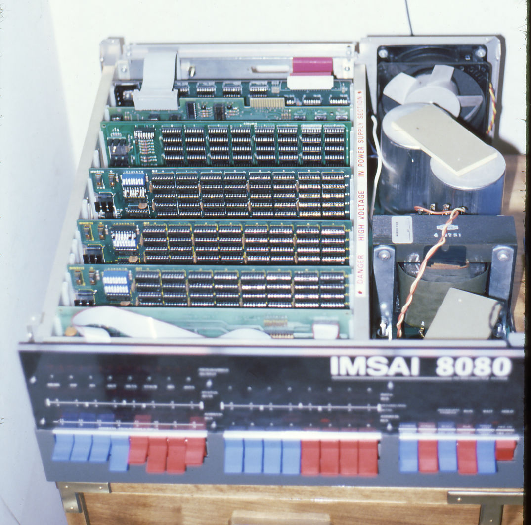
I’ve had an actual IMSAI 8080 computer since about 1976. I purchased it as a kit. The kit came with all the parts needed for the computer except RAM so I purchased an S-100 4K RAM card kit as well. Here is a photo I took of it just after I completed the kit. You couldn’t do much with it at this point. The best you could do was enter a program in binary machine language one byte at a time via the front panel switches and run it. (A very laborious task.) The only output was a set of 8 LED’s (also on the front panel) connected to an I/O port.

It wasn’t much, but it was all I could afford on grocery sacker’s pay. I was taken with computers. My 12th grade math teacher had introduced me to the binary and hexadecimal numbering systems and their relation to computers. I bought issues of Byte and Kilobaud magazines and absorbed as much as I could understand. In college I took an elective Intro to Programming class. I learned IBM/360 assembly language in that class. I loved it so much I was convinced that I had to get a computer of my own. Hence the IMSAI 8080 kit and all my money.
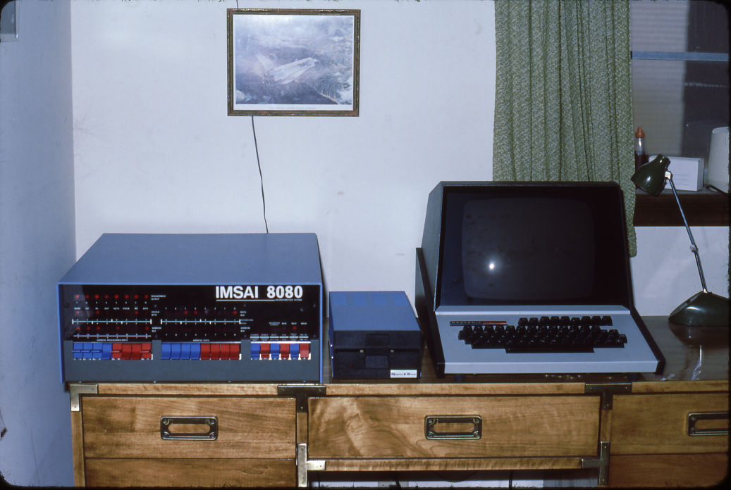
After a disastrous semester at OU I went back to Tulsa Community College and enrolled as a computer science major. After my first year, the school hired me as an assistant systems programmer. I was now making enough money that I bought three more memory card kits (now I had 64K RAM), a serial interface card kit, and a new and amazing 5.25″ floppy disk drive and controller. Here is a photo of the upgraded machine.
I also bought a Heathkit serial terminal kit. Here is my complete system.
It was great. I worked during the day on the IBM/360 mainframe and then came home and worked on my own computer. It was great fun. But, as they say all good things…
The Heathkit terminal bit the dust. I did a lot of troubleshooting but couldn’t get it working. Shortly thereafter I got married. Now there were other priorities and the IMSAI 8080 kept getting lower and lower on the list. Plus, personal computers were proliferating. I eventually got an Atari 800 system and even did a bit of freelance work with it. By this time I had a new job and the IBM PC revolution changed almost everything.
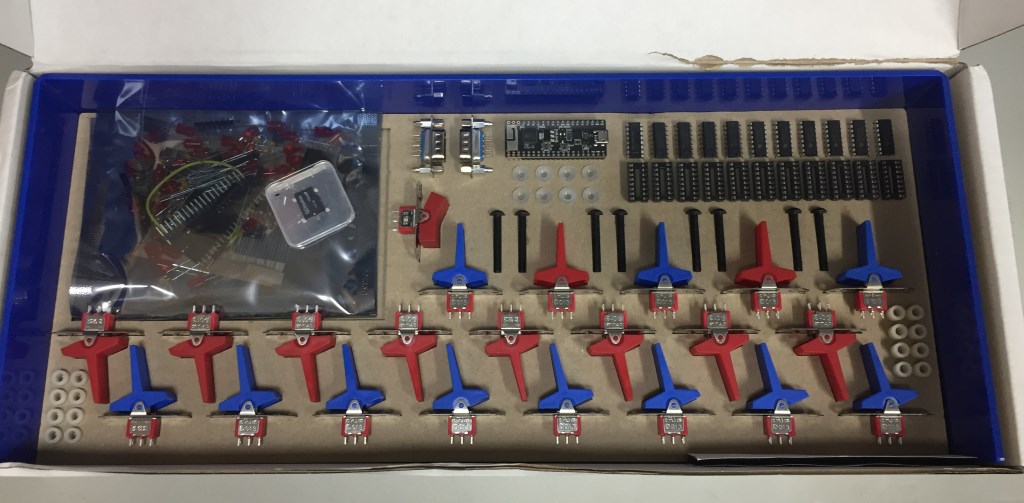
However, I always had a soft spot for the IMSAI. Enter The High Nibble. I saw a YouTube video of his IMSAI clone kit. He used an ESP32 single board computer to run the z80pack emulation of an IMSAI 8080 running either an Intel 8080 or a Zilog Z80. He also created a near exact replica of the IMSAI 8080 front panel. I had to have one. It arrived from Australia in a very nice box and inside was an equally nice and professionally packed kit. The kit replicated the front panel almost exactly from the red and blue switches to the clear plexiglass front panel graphics. Here is the kit and some of the packaging.
The next layer down from the switches and components were the rest of the front panel parts.
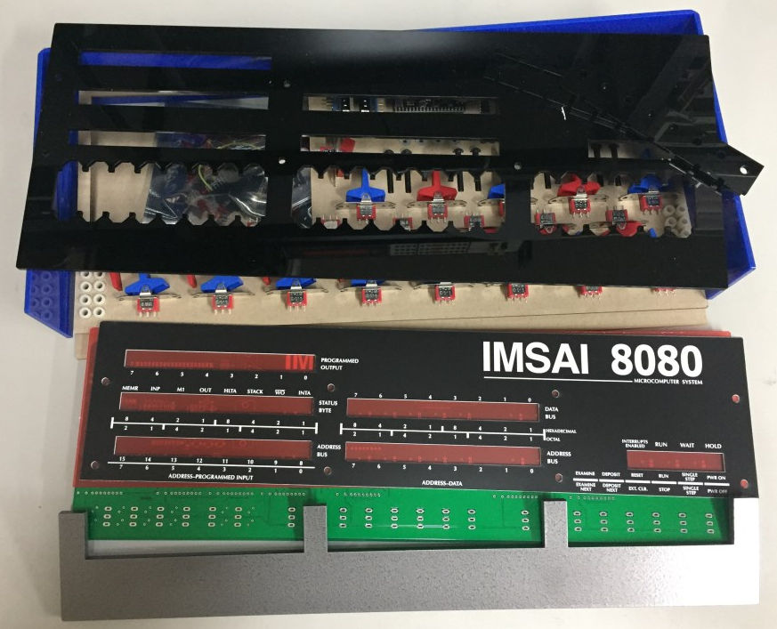
The front panel circuit board looked nice. There were two surface mount components that intimidated me a bit. I’ve never soldered a single surface mount part before.

The kit sat for a bit while I gathered all the items I would need to assemble it. I needed a new soldering iron, a flux pen, thin gauge solder and a number of other useful tools that were suggested in another of his YouTube videos. I then started the assembly with the surface mount parts. Here is a closeup of the PSRAM chip and the micro SD card holder. Fortunately those were the only surface mount parts.
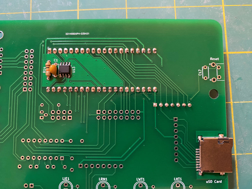
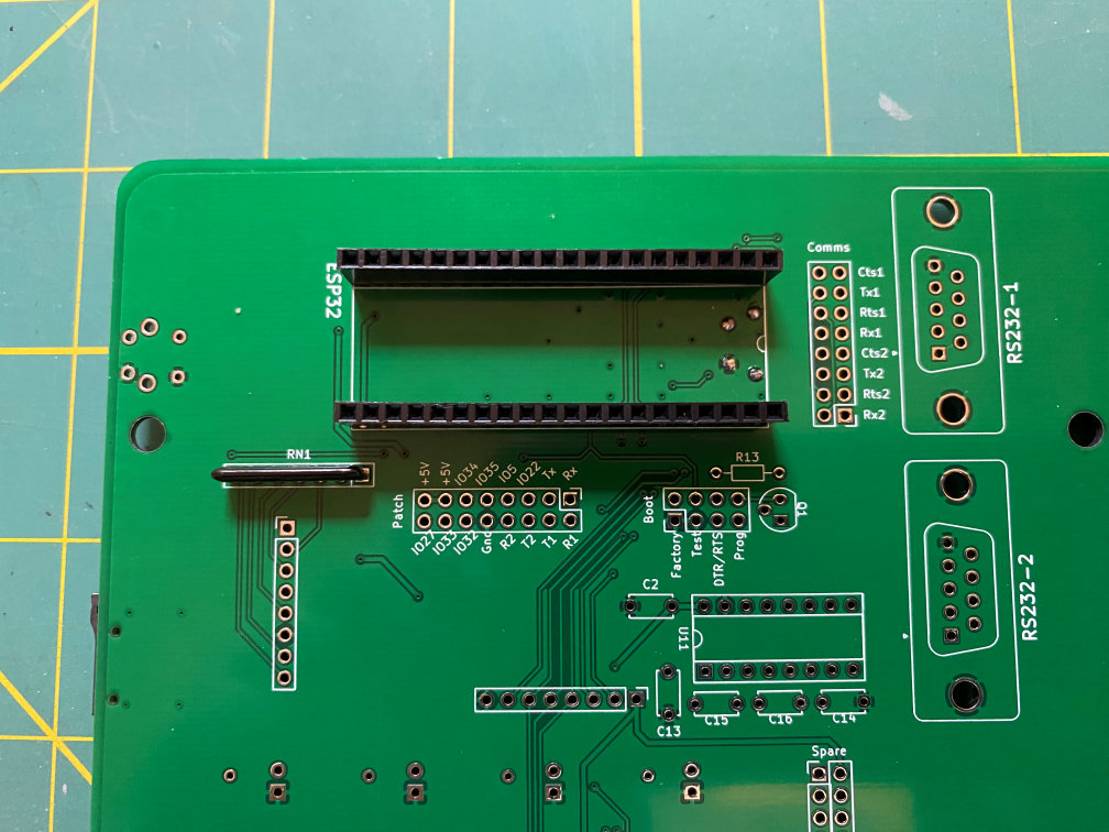
I could have done a better job on the PSRAM chip but all the solder joints tested out fine. The microSD card holder turned out pretty well. Its pins were a bit closer together than the PSRAM. With these types of parts a flux pen is definitely your friend. Then the board was turned over and the headers for the ESP32 board and a resistor network were soldered in.
Next up was the process of soldering in the LEDs. The kit has a nice tool to provide the right spacing between the board and the base of the LEDs.

The 45 LEDs were then soldered in place along with their resistors. Then the IC sockets with some capacitors were added.

Once again the board was turned over and a socket and some capacitors were soldered in.

Back on the front side some control switch resistors were added as well as a reset switch on the upper right of the board.

Then the remaining components (other than the switches) were soldered on the back side.
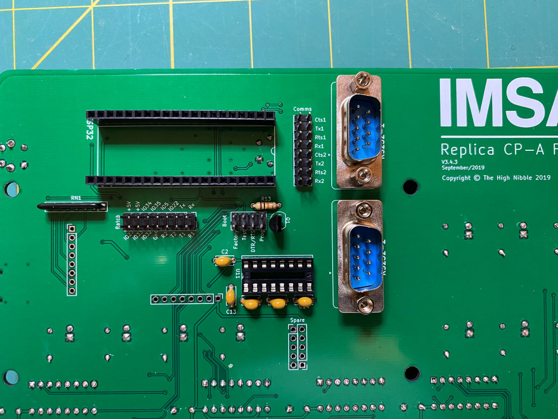
It pretty much consisted of the two RS-232 connectors and some headers for configuration jumpers and an expansion header. Once all that was done the ICs were inserted into their sockets.
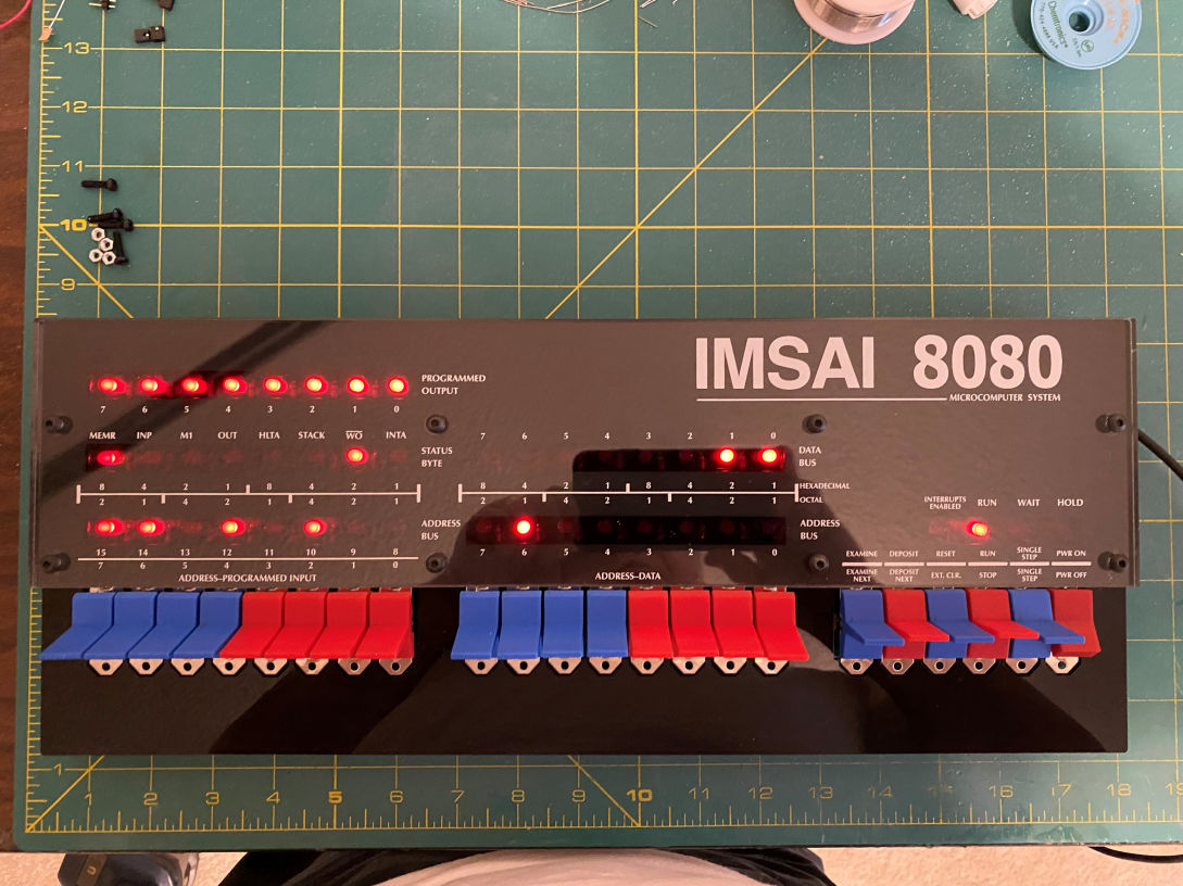
Now it was time to do a test. The ESP32 board was installed on the back side. The microSD card was inserted into its slot. Then the power switch was press fit into its spot on the front of the board. I plugged a micro USB charger into the ESP32 board and gave it a few seconds to boot up. I then turned on the power switch. Yipee! The LEDs lit up just like they were supposed to. Here is a photo.

I was able to use the probe wire that was provided and jumpered a couple of the switches and made sure that all the lights came on as they were supposed to. Now it was time to add the switches. I unplugged the USB cable and removed the power switch, microSD card, and the ESP32.
The kit provided a template to make sure the switches were in their correct place. There was also a jig that would hold the switch paddles in a straight line while they were soldered in. It was all kept together with a couple of rubber bands. That really made it a lot easier to turn the board over without moving everything around.

Here it is with all the switches soldered in.

Now it was time bolt it all together.
Of course I had to plug it in one more time to see the look. It looks just like the original. But there was one other thing I forgot to get many pictures of while building it. My version of the kit had added some corner reinforcements to the clear back panel. The original kit did not have these and the designer was getting some feedback that the corners of the clear back panel were cracking after tightening the bolts that hold the outer case on. The reinforcements allow the nuts to be captured and even out pressure when the bolts are tightened. He indicated the best glue was acrylic cement, but I didn’t have any. But I did have a powerful solvent, Methylene Chloride, that I use to build my plastic model kits. I did a Google search and it appeared that it would bond acrylic. I applied it to the reinforcements, and sure enough it does an excellent job. Here is the back with the reinforcements installed.

Here is a closeup of one corner near the ESP32. One of the corner pieces was chopped on one side. That was supposed to go on the side of the clear back where the ESP32 sticks out. This is to relieve any stress on the USB socket of the ESP32. Well, I got my backsides confused and glued it on the wrong side. That forced me to break out the Dremel and grind off a portion of the misplaced corner piece. After a couple of test plugs I had it ground down where it was out of the way of the USB cable. Here is a close up. You can just barely see the one I glued on the wrong side.

Now it is complete and I have the outer case bolted on. Here is a picture of the front and a back side of the completed kit.


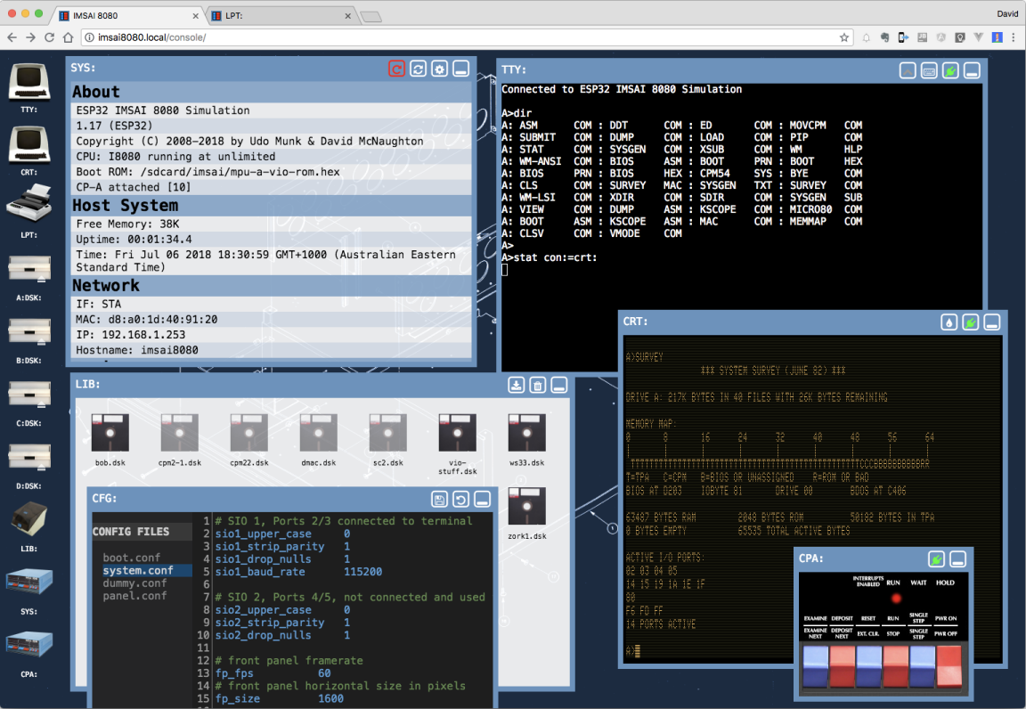
I don’t have anything to plug into it, but The High Nibble has thought of that. The ESP32 provides a wireless connection and a web interface that includes a virtual TTY, CRT, line printer and other virtual tools to interact with the IMSAI 8080. Here is a screen grab from The High Nibble web site.
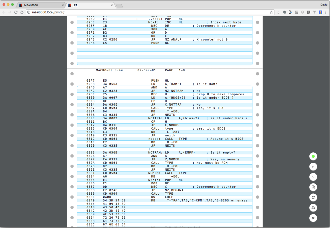
Here is an example of the output from the virtual line printer.
All in all this is a very good kit of a vintage PC. Since I bought this kit The High Nibble has created an add on card that will allow you to connect a monitor and keyboard, which makes this a standalone machine. I’ll be working on that kit (S-132) soon.
This was fun and now I have a working IMSAI 8080 (clone) again.
Thanks for looking.

One thought on “IMSAI 8080 Clone Kit”