
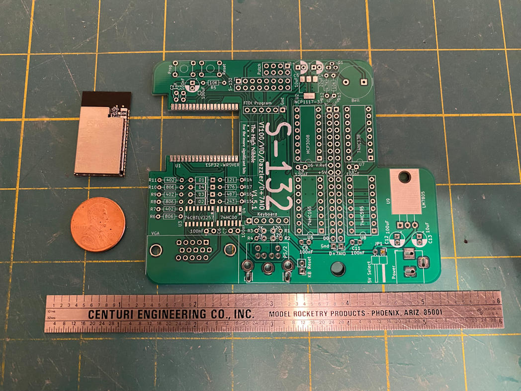
Here is the S-132 kit from The High Nibble. It adds many features that were provided on the real IMSAI 8080 by add-in S-100 cards. It provides output to a VGA monitor and supports either a PS/2 or USB-HID keyboard for input. You have to choose one or the other the board does not support both. I ordered my S-132 with the USB-HID port. The device simulation is done via an onboard ESP-32. This is in addition to the ESP-32 that runs the IMSAI 8080 emulator. It connects to the IMSAI 8080 clone via the patch header that is provided. Here is a picture of the S-132 board.
I would have to flash new firmware to my IMSAI 8080’s ESP-32 to support the S-132. Not only did this firmware upgrade add support for the S-132 is also allows the IMSAI 8080 to emulate either the original IMSAI 8080 computer but also the Cromemco Z-1 computer. The Cromemco system supported multiple CRT’s and had an operating system that supported multiple users. So the S-132 emulates a slightly different set of devices depending on what firmware you are running. Here is a list of the several S-100 attached devices it provides.
- VT-100 terminal
- Two additional VT-100 terminals in Cromemco mode
- IMSAI VIO S-100 card in IMSAI 8080 mode only
- Cromemco Dazzler S-100 card (either mode)
- Cromemco D+7A input/output S-100 card (either mode) for digital and analog input and output
- Adds the ability to add 2 Cromemco JS-1 joysticks
- A Centronics parallel printer port (DB-25)
It also adds access to the SYS: interface without using the web interface. This allows you to mount and dismount floppy disks without using the web interface. It also provides a barrel jack to add a 5v to 12v power supply that can power both the IMSAI 8080 and the S-132 without needing to use the USB port of the ESP-32.
In the above photo the object above the penny is the ESP-32. There are a few more surface mount parts on this board, namely a couple of IC’s, a linear regulator, and the ESP-32. The ESP-32 was the part that intimidated me the most. Those are a lot of pins that need to be soldered and they are quite close together. I taped the ESP-32 to the board to hold it in place until I got a few of the pins soldered. Here’s a picture.
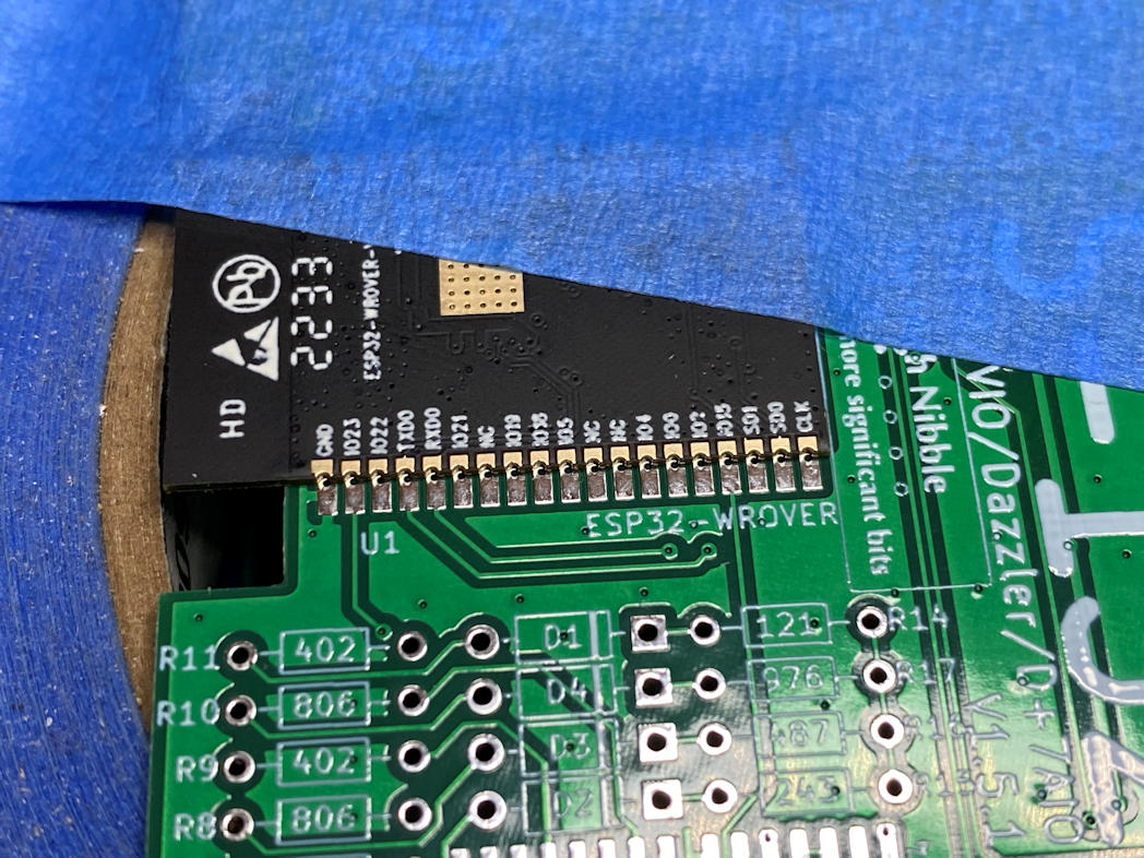
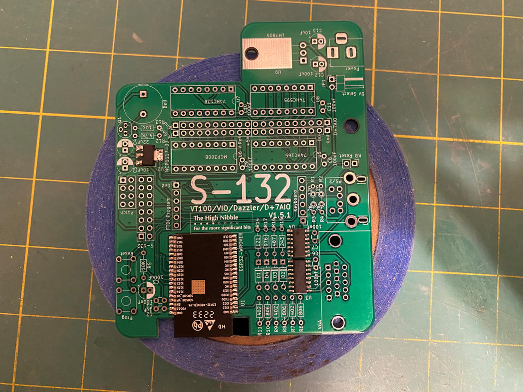
I used the narrowest tip I had for my soldering iron and a lot of flux. The key was to get the solder on both the pad and the side of the pin. This would create a good solder joint and the flux should help prevent bridging the the pins. Here it is all soldered in place.

For me it was a bit stressful but visibly successful attempt. I won’t know if I got it right until it’s all done and I power it up. Next I soldered in the remaining three surface mount components. I placed the board on a roll of painters tape so I had a stable surface. The ESP-32 has a heat spreader on the other side that extends beyond the board and would make the board tip one way or another while I was trying to solder on the other components. This made the board stable during soldering.
I decided that I would solder the rest of the components from shortest to tallest. That meant I started with the resistors and diodes.

I then continued on with the other components.
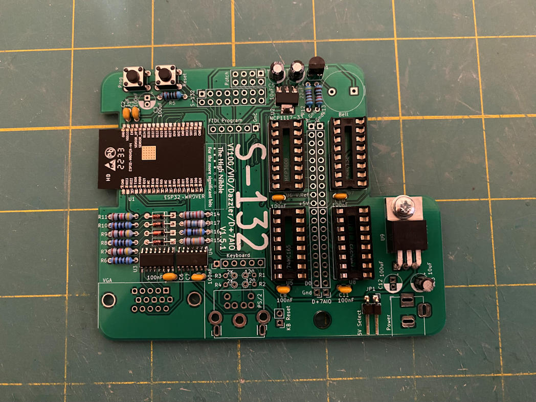
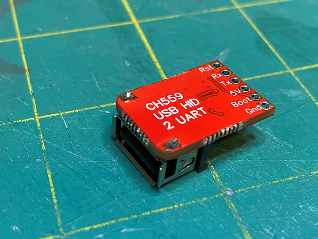
Now all that was left were the USB-HID miniboard, headers, large capacitors, barrel jack, and VGA port. I started with the USB-HID miniboard. It was meant for it to sit flat against the main S-132 board. The mini board has an IC on it that would have been a nightmare to solder, but fortunately this mini board is pre-soldered. The only problem was that the two pins that hold the USB socket in place had been soldered with an abundance of solder. This prevented me from getting a good flat join. I use some solder wick and remove a lot of the excess, but it still stands up just a bit. I did apply a good amount of solder from the back side of the S-132 to get a firm attachment to the board. It should work.
The rest of the parts were soldered in place with no trouble. Here is a view of the completed board.

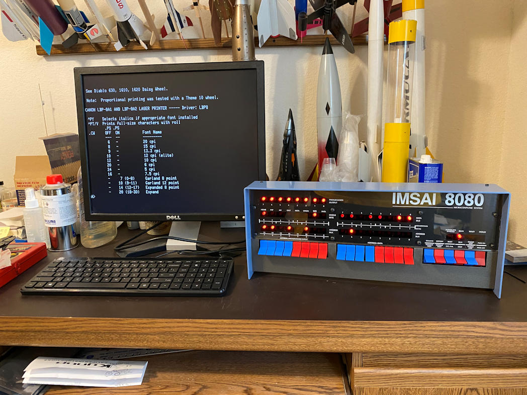
I finished flashing the new firmware on the IMSAI 8080 and making a new uSD card to support the changed firmware. I installed the S-132 on the patch header on the IMSAI 8080. Then connected an old Dell flat panel monitor to the VGA port and I connected an HP keyboard that I’d had in its original box for a few years to the USB port. I then plugged in power and watched the monitor. I heard a beep and then a cursor square appeared on the screen. So far so good. I then flipped the power switch on the IMSAI 8080. The lights came on as usual. Then I clicked the RUN switch. Almost immediately the screen changed to the CP/M start up and I got an “A:” prompt. I did a DIR command. The system took it and the disk contents came up. Next I did a TYPE command for a CP/M text file and it scrolled across the screen. See below.
Fantastic! I now have a standalone IMASI 8080 clone. It should work just like the real IMSAI 8080 and Heathkit CRT that I had all those years ago. Now to dig through the old software and see what I can do with it.
Thanks for looking in. Although the holidays are in full swing, I’m hoping to start a new model build soon.
