

I was browsing the web the other day and hit upon some pages about the IMSAI 8080. One of the very early personal computers. It reminded me that I’ve got an IMSAI8080esp clone by the High Nibble that I built a while back. After building it and toying around with it for a few weeks, I had put it back in its box, stored it away and then forgot about it.
I pulled it out of the box and hooked it up. That’s a photo of it above. It occurred to me that I should write a little program to animate the 8 output LEDs on the front panel. I had seen some DEC PDP-11/70 front panel kits on YouTube. Several of them had some of the front panel lights that ran a continuous pattern. I think they call it Blinkenlights. There’s no reason I couldn’t do something similar for my IMSAI clone.
I remember back in 1976 when I finished building my original IMSAI 8080. It cost $500 for a kit of parts. Today that’s equivalent to over $2800. That’s a photo of it below. I found a listing for a little game that was about 20 or so bytes of Intel 8080 machine code. It was called “Kill the Bit”. I keyed it into the computer using the front panel switches. Then set the address of the first byte of the program and hit the run button. On the output port a single LED would move from bit 8 to bit 1 and then recycle. The object was to turn off the LED by clicking the switch below the LED that was lit before it moved. If you matched it, the LED would turn off. If you missed, an additional bit would appear that you would now have to turn off. You won by turning off all the LEDs.

Now, a few decades later, I have a clone of that computer. Rather than write a game, I decided to write a program to display a series of patterns on the 8 LEDs of the front panel. I could write it in BASIC, but why not get closer to the hardware and write it in 8080 assembly language.
One reason I decided to do an assembler program is I’ve always enjoyed writing in assembler. Higher level languages such as BASIC or C are easier to write, but each line of a high level language generates many lines of equivalent assembler code. In general, you trade ease of use for larger programs. When you’ve got less than 64 kilobytes of memory, smaller is better. Consider that 64 kilobytes is about 0.000003814697265625% of the memory that one of today’s PC’s have. Many of which come with 16 gigabytes of memory.
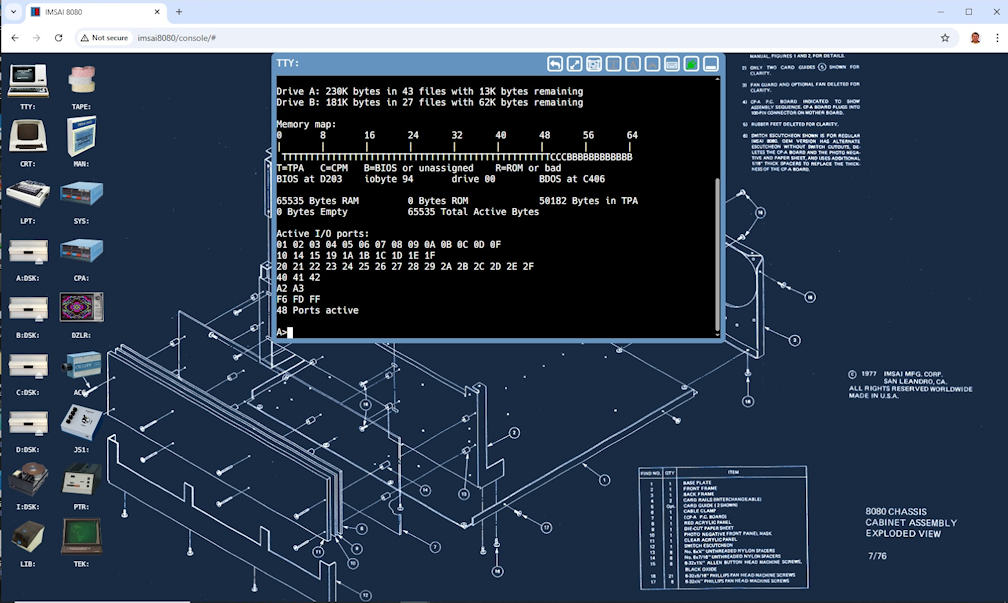
The IMSAI8080esp comes with a set of virtual floppy disks that contain vintage software. I’m running the CP/M 2.2 operating system, an early ancestor of MS-DOS. Among other things it comes with a compiler, ASM, to compile assembler programs and turn them into files that will run on the machine. You need an editor to create the assembler source file. A editor called ED comes with CP/M. Below is a screen shot of the IMSAI8080esp desktop. It shows the TTY: virtual device which emulates a VT100 terminal. The TTY: screen is showing the output of the CP/M SURVEY command. It gives an overview of the running CP/M system. The icons on the left side are other virtual devices that can be used.
A word processor called WordStar can also be used for the same purpose as ED and is on another virtual disk. WordStar is a bit more complicated but is also more versatile. I decided to go with WordStar. Fortunately, documentation for the ancient program is still available. Below is a screen shot of using WordStar to enter the program.

It’s been a long time since I’ve used the 8080 instruction set. My career has been working in the IBM mainframe world. Needless to say the instruction set of an early microprocessor is much more primitive than a mainframe. The registers (high speed storage locations) are only 8 bits (one byte) wide. The IBM mainframes I’ve worked on had registers at least 32 bits (four bytes) wide. While the mainframe has instructions that can directly modify or move data in RAM memory with only a single base address loaded into a register. The 8080 needs to involve its registers to not only address the memory but to also move data from one location to another. Below are sections of reference cards showing some of the instructions of each machine.


Another difference is the use of a stack. An IBM mainframe doesn’t directly involve the concept of a stack, while an 8080 microprocessor is very much a stack based machine. You can think of a stack as a group of contiguous memory locations that is reserved for storing and retrieving register values. A stack has a starting point and when you push (store) a register value on the stack the stack pointer is modified to point to the next available stack slot. In the case of the 8080 the stack builds from the bottom up. When you pop (retrieve) a value from the stack to load a register the stack pointer moves back a slot. It is a serial resource so values that pushed onto the stack are popped out in reverse order. In the case of the 8080 each stack slot is two bytes long. You need to be sure that your stack is large enough for your purposes or you will start overwriting memory outside of the stack. You can’t tell the microprocessor how large the stack is, it just assumes that the next slot is free to write to.
When you push a register onto the stack it actually stores a register pair. The 8080 has a set of registers labeled A, B, C, D, E, H, and L, each of them 8 bits wide. There is also a stack pointer register called SP it is the only register that is 16 bits wide since it assumed that it will always contain a memory address. Anything loaded into the SP is assumed to be the address of a stack. The A register is called the accumulator and is a special register that performs math and logical operations. The other registers can be used individually or in pairs. The pairs are B/C, D/E and H/L. So when you push the B register you actually push both the B and C registers. B is pushed first then C. To load data from the stack you do a pop. If you pop into the B/C pair, C is loaded first then B. You can also push a special pair called the PSW. It consists of the accumulator and the status byte.
In the earlier screenshot showing WordStar, you can also see the beginning of the program. I’ve named it Liteshow. The beginning is where I save CP/M’s stack pointer and then set the stack pointer to my own stack. The code with the label “EPILOG” is were the program will exit. It reloads CP/M’s stack pointer and then returns to CP/M.
The status byte is a control register where each bit is a flag that represents the current state of the machine. For example, there is a carry flag that indicates when a math function causes the value of the accumulator to overflow or underflow its 8 bits. There is a zero flag that indicates whether the previous instruction resulted in a zero value. It also has a parity flag to indicate the parity of the accumulator. The parity flag is set if the sum of the bits is even. If the sum is odd the parity flag is cleared. For example, if the accumulator contains the number 5 it would have the bit pattern “00000101”. The count of the set bits is 2, therefore the parity is even. There are two other flags, but I’ve gone on long enough about the status byte.
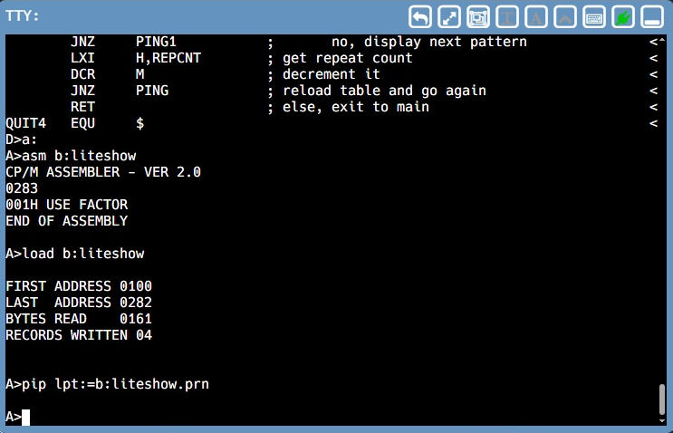
Sometimes when you are programming and have a bug you’re trying to squash, you need a print out. The CP/M assembler produces a .HEX file that contains the machine code. It also produces a .PRN file that has a printout of the assembly. Any lines with an error are marked. The IMSAI8080esp has a virtual line printer. To print your assembly to the virtual printer you use the PIP command as shown below.
If you click the LPT: icon on the IMSAI8080esp desktop you can view what is on the printer as shown below. You can get an actual paper print by clicking the printer icon on the right hand side.

This program will be writing a series of bit patterns to the output section of the front panel. (The eight LEDs in the upper left on the front panel.) The first pattern will move a single bit from left to right then wrap around and do it again. The next pattern will be the opposite, right to left. The third pattern will run a single bit from left to right then, instead of wrapping around, it will then go from right to left. Kind of a bouncing pattern. Lastly, a pattern of two bits will start at the outer edges and move to the center. When they meet in the middle it will reverse and go back to the edges.
The first two patterns are basically the same except for the direction. All I need to do is start with a pattern of binary bits ‘1000000’ (80 in hexadecimal) then rotate the bits to the right one bit at a time until the bit pattern is ‘00000001’ and then start over with ‘10000000’. The second one will do the same except it would start with ‘00000001’ and rotate the bits to the left. The third one will simply combine the two and do one pass rotating right and then one pass rotating left. The final pattern will start with ‘10000001’ (81 hex), then ‘01000010’ (42 hex), ‘00100100’ (24 hex), ‘00011000’ (18 hex). Once at the center, it will run the pattern backwards.
Even though this is a slow early generation microprocessor (4Mhz clock), it still runs quite fast compared to a human. If I let the pattern run at machine speed, you would barely notice that the LEDs were flashing. To make it that a person can actually see the changes I need to put in a delay loop each time I output a new pattern. To accomplish this, I load the B/C pair with 7 at the top of the program. Then I load the H/L pair with 0 for each pattern change. At the end of each output I add B/C to the 16 bit value in the H/L pair. This means that I’m counting from 0 to 65,536 by 7’s. 65,536 (64k) is the maximum value of that can be contained in 16 bits. When the count overflows the carry bit is set and I know I’ve waited long enough and then continue with the rest of the program.
I want the program to run continuously. Therefore the main part of the program is a loop that resets a repeat counter (currently 10) and then runs each pattern as a subroutine, sequentially. When if finishes the last pattern, it loops back to the top and does it all over again. Of course, if that was all it did, the only way to stop it would be to press the stop key on the front panel, enter a zero address on the front panel, then press the run key. Restarting at address 0 on a CP/M 2.2 machine performs a warm restart getting you back to the familiar A> prompt.
I’d rather be able to just press a key on the keyboard and have the program exit by itself. The easiest way to do that is to call a BDOS routine. CP/M puts BDOS routines in high memory to allow other transient programs to use CP/M services for various functions rather than have the transient program contain them. This can make transient programs smaller and leverages the work that CP/M has already done.
You perform a BDOS routine by executing a CALL instruction to address 0005h. To tell BDOS which function to use you place a function code in the C register. If the particular BDOS function you are using needs additional information you load those values into various other registers depending on which BDOS function you are using. In my case I’m going to use function 06h which is direct console I/O. Function 6 needs to know if this is an input or an output operation. I’m wanting to look for input so I put FFh into register E. When function 6 returns, the A register will contain either the character that was input or 0 if no character is ready. So all I need to do is call function 6 and then compare A to zero. If A is not zero then I need to exit. I do that by turning on an exit flag which will be checked later. Since I will be checking for input at many different places in the program, I created a subroutine to do the function call.
Once the pattern has completed its first pass I need to do it 9 more times. At this point I do a keyboard check and if the exit flag is off I get the repeat count and decrement it by one. If the count is not zero then I go back and do another pass, otherwise I return to the main loop.
With all that defined I wrote the program as shown below. There were a few times when I did some silly things that caused the program to not come anywhere close to doing what I wanted. But, with careful reading of the code and referring to the language manual I finally got past them all. I could go in and try to make it more efficient in a few areas, but it does what I want it to do, so I’m happy.
If you made it this far, thanks! Here is a short video showing it in action. If you want to see the actual program, below the video is my code and explanation. If you’re leaving at this point, thanks for at least making it to here. Sometimes I’m a little passionate about programming and I get carried away. So for the nitty gritty scroll past the video.
The opening code:
ORG 0100h ; tell assembler where program will start
LXI H,0 ; clear H/L pair
DAD SP ; add SP to H/L
LXI SP,MYSTACK ; load SP with our stack pointer
PUSH H ; save CP/M stack pointer
CALL MAIN ; start our program
;
EPILOG POP H ; get CP/M’s stack pointer
SPHL ; load SP with CP/M’s stack pointer
RET ; return to CP/M
; stack definition
DS 32 ; define 16 word stack
MYSTACK EQU $ ; set constant for our stack address
; define data areas here
PAT DS 1 ; storage for bit pattern
REPCNT DS 1 ; counter for repeating patterns
QF DB 0 ; quit flag – 0 = OK, FFh = quit
PBITS DB 081h,042h,024h,018h ; part 1 of table for PING
DB 024h,042h,018h,0FFh ; 0FFh marks end of table
; define constants here
DELAY EQU 07h ; delay value: higher = faster
PORT EQU 0FFh ; output port number for LEDs
BDOS EQU 05h ; BDOS entry point
FUNCT EQU 06h ; BDOS function 6 – console i/o
INPUT EQU 0FFh ; BDOS function – 6 get input
ABORT EQU 0FFh ; program quit flag
This code sets the starting address for the program and sets up a local stack. It then calls the main program. The lines following ‘MYSTACK’ define the data areas the program will use. Finally the constants are defined. They are symbolic only and do not take up any storage.
The below code defines the main program loop.
; program begins here
MAIN EQU $ ; start of main program
LXI B,DELAY ; load delay value into B/C
RESET EQU $ ; top of main loop
MVI A,0Ah ; set to repeat pattern 10 times
STA REPCNT ; save it to the repeat counter
CALL PATRT ; call the rotate right pattern
LDA QF ; get quit flag
CPI ABORT ; is quit flag set?
JZ DONE ; yes, jump to end code
MVI A,0Ah ; set to repeat pattern 10 times
STA REPCNT ; save it to the repeat counter
CALL PATLF ; call the rotate left pattern
LDA QF ; get quit flag
CPI ABORT ; is quit flag set?
JZ DONE ; yes, jump to end code
MVI A,05h ; set to repeat pattern 5 times
STA REPCNT ; save to repeat counter
CALL PPPAT ; call the bouncing pattern
LDA QF ; get quit flag
CPI ABORT ; is quit flag set?
JZ DONE ; yes, jump to end code
MVI A,0Ah ; set to repeat pattern 10 times
STA REPCNT ; save it to the repeat count
LDA QF ; get quit flag
CPI ABORT ; is quit flag set?
JZ DONE ; yes, jump to end code
JMP RESET ; jump back to top of loop
DONE EQU $
MVI A,0 ; prepare to clear output
OUT PORT ; clear the outpu LEDs
RET ; return to EPILOG code
The main loop calls each pattern in sequence. After the pattern routine returns the quit flag is tested. If it has been set then the loop jumps out to the DONE label which resets the LEDs and returns to the opening code. If the quit flag is not set then the loop continues.
Next the keyboard check routine is defined.
; check keyboard input subroutine
CKKB EQU $
PUSH B ; save registers
PUSH D
PUSH H
MVI C,FUNCT ; bdos call 6 – console i/o
MVI E,INPUT ; set for console input
CALL BDOS ; check for input character
POP H ; restore registers
POP D
POP B
RET
The first thing it does is save the registers that will be used. Then it sets the BDOS call number and indicates that the function is for input. It then calls BDOS. Then it restores the registers and returns to the routine that called it.
Next comes the pattern routines, starting with the left to right pattern.
; pattern routines
PATRT EQU $
MVI A,080h ; set initial bit pattern
STA PAT ; store it
LXI H,0 ; initialize H/L delay counter
BEG1 EQU $
LDA PAT ; load bit pattern
CMA ; invert A
OUT PORT ; output the pattern
DAD B ; increment the display counter
JNC BEG1 ; if delay not expired output again
; delay expired, change pattern and go again
LDA PAT ; get pattern
RRC ; shift pattern right
STA PAT ; save the new pattern
JNC BEG1 ; if not pattern end, continue
; if end of pattern check abort and repeats
CALL CKKB ; check for keyboard input
CPI 0h ; keypress ready?
JNZ QUIT1 ; yes, time to stop
LXI H,REPCNT ; get address of repeat counter
DCR M ; decrement repeat counter
JNZ PATRT ; repeat pattern
RET ; exit to MAIN
QUIT1 EQU $
MVI A,ABORT ; get quit flag
STA QF ; save the quit flag
RET ; exit to MAIN
The routine starts by loading its beginning pattern. Then saves it so it can be retrieved later. Then the H/L pair is set to 0. The output loop is next, starting by reloading the bit pattern. A quirk of the output LED panel is that it displays the inverse of the value that is output. If the value is ‘1000000’ then the display shows ‘01111111’. So to display what I actually want I need to invert the value. That is what the CMA instruction does. The DAD instruction adds the value of the specified register pair to the H/L pair. IF the H/L pair overflows the carry bit is set. If the carry bit is not set then the output loop is performed again. If it carry bit is set, then the pattern is reloaded and rotated to the right and stored for the next pass. If the rotate pushes a 1 bit out then the carry flag is set otherwise it is cleared. If the carry flag is set it jumps to the start of the output loop to do the next pattern.
At the end of the pattern pass a call is made to check for keyboard input. If the return value is not 0 then it jumps to the quit section which sets the quit flag and exits back to the MAIN routine. If the value is 0 then the address of the repeat counter is loaded into the H/L pair and the value at that address is decremented by 1. If the repeat counter is not zero then the pattern pass is repeated, otherwise the routine exits to MAIN.
I think I need to clarify the DCR instruction. The M that follows DCR is not label for a memory location nor is it a register name. Instead it is a special mnemonic that indicates the byte to be decremented is addressed by the H/L pair.
The next routine called by MAIN is the right to left pattern. It is exactly the same as the the above routine, but instead of using an RRC it uses an RLC to rotate the pattern to the left.
;
PATLF EQU $
MVI A,001h ; set initial bit pattern
STA PAT ; store it
LXI H,0 ; initialize H/L delay counter
BEG2 EQU $
LDA PAT ; load bit pattern
CMA ; invert A
OUT PORT ; output the pattern
DAD B ; increment the display counter
JNC BEG2 ; if delay not expired output again
; delay expired, change pattern and go again
LDA PAT ; get pattern
RLC ; shift pattern left
STA PAT ; save the new pattern
JNC BEG2 ; if not pattern end, continue
; if end of pattern check for abort and repeats
CALL CKKB ; check for keyboard input
CPI 0h ; keypress ready?
JNZ QUIT2 ; yes, time to stop
LXI H,REPCNT ; get address of repeat counter
DCR M ; decrement repeat counter
JNZ PATLF ; if not 0, repeat pattern
RET ; exit to MAIN
QUIT1 EQU $
MVI A,ABORT ; get quit flag
STA QF ; save the quit flag
RET ; exit to MAIN
The next pattern routine is the ‘bounce’ pattern. It is a combo routine using parts of both PATRT and PATLF.
;
PPPAT EQU $
MVI A,080h ; set initial bit pattern
STA PAT ; store it
LXI H,0 ; initialize H/L delay counter
PPR EQU $
LDA PAT ; load bit pattern
CMA ; invert A
OUT PORT ; output the pattern
DAD B ; increment the display counter
JNC PPR ; if delay not expired output again
; delay expired, change pattern and go again
LDA PAT ; get pattern
RRC ; shift pattern right
STA PAT ; save the new pattern
JNC PPR ; if not pattern end, continue
; if end of pattern check for abort and repeats
CALL CKKB ; check for keyboard input
CPI 0h ; keypress ready?
JNZ PPQUIT ; yes, time to stop
;
MVI A,001h ; set initial bit pattern
STA PAT ; store it
LXI H,0 ; initialize H/L delay counter
PPL EQU $
LDA PAT ; load bit pattern
CMA ; invert A
OUT PORT ; output the pattern
DAD B ; increment the display counter
JNC BEG2 ; if delay not expired output again
; delay expired, change pattern and go again
LDA PAT ; get pattern
RLC ; shift pattern left
STA PAT ; save the new pattern
JNC PPL ; if not pattern end, continue
; if end of pattern check for abort and repeats
CALL CKKB ; check for keyboard input
CPI 0h ; keypress ready?
JNZ PPQUIT ; yes, time to stop
LXI H,REPCNT ; get address of repeat counter
DCR M ; decrement repeat counter
JNZ PPPAT ; repeat pattern
RET ; exit to MAIN
PPQUIT EQU $
MVI A,ABORT ; get quit flag
STA QF ; save the quit flag
RET ; exit to MAIN
The final pattern called PING and is a double bit pattern stored in the table PBITS near the top of the program. In the case of this pattern, rather than rotating the pattern the table pointer is incremented to obtain the next bit pattern. The other checks are very similar to what I’ve done previously.
;
PING EQU $
LXI D,PBITS ; get address of PBITS table in D/E
LDAX D ; get pattern from the table
STA PAT ; store pattern
PING1 EQU $
LXI H,0 ; initialize H/L delay counter
BEG4 EQU $
LDA PAT ; load the bit pattern
CMA ; invert A
OUT PORT ; output the pattern
DAD B ; increment the display counter
JNC BEG4 ; if delay not expired output again
; delay expired, change pattern and go again
INX D ; increment the table pointer
LDAX D ; get pattern from the table
STA PAT ; save the new pattern
CALL CKKB ; check for keyboard input
CPI 0h ; keypress ready?
JNZ QUIT4 ; yes, time to stop
LDA PAT ; get new pattern
CPI 0FFh ; end of table?
JNZ PING1 ; no, display next pattern
LXI H,REPCNT ; get address of repeat counter
DCR M ; decrement repeat counter
JNZ PING ; if not zero reload table and go again
RET ; else, exit to MAIN
QUIT4 EQU $
MVI A,ABORT ; get quit flag
STA QF ; save the quit flag
RET ; exit to MAIN
;
END 0100h
This final routine gets the address of the pattern table into the D/E pair, gets the first pattern and saves it. It then clears the delay counter and drops into the display loop. When the delay counter expires it increments the D/E pair to point to the next table entry and loads that byte into A. After saving the new pattern, it checks for keyboard input and if there was some, it jumps to the quit section. Otherwise, it gets the new pattern and if it is not the end of table marker it jumps to the display section. If it is the end of the table, it decrements the repeat counter. If the repeat counter in not 0 then it jumps to the start of the routine to reload the table pointer. Otherwise it returns to the MAIN routine.
Well that’s it. I hope you got something out of this VERY long winded post. I had a lot of fun writing the program. In the next post I will be back to work on the 1/48 scale Atlas D model. Thanks for visiting.

This is such a great blog post and an awesome blog I found because I was googling the imsai-8080 replicas. I see you’ve been writing this since 2008. keep it going Luhman! I like the miniature kits you paint as well, you should paint a warhammer 40k mini for fun.
thanks
Tom
Thanks for the kind words. I’m glad you liked the post. I plan on keeping it up. I try to get them out once a week, but somehow I find retirement busier than when I was working.
Randy