
A little more work got done on the Dragon model in the last few days.
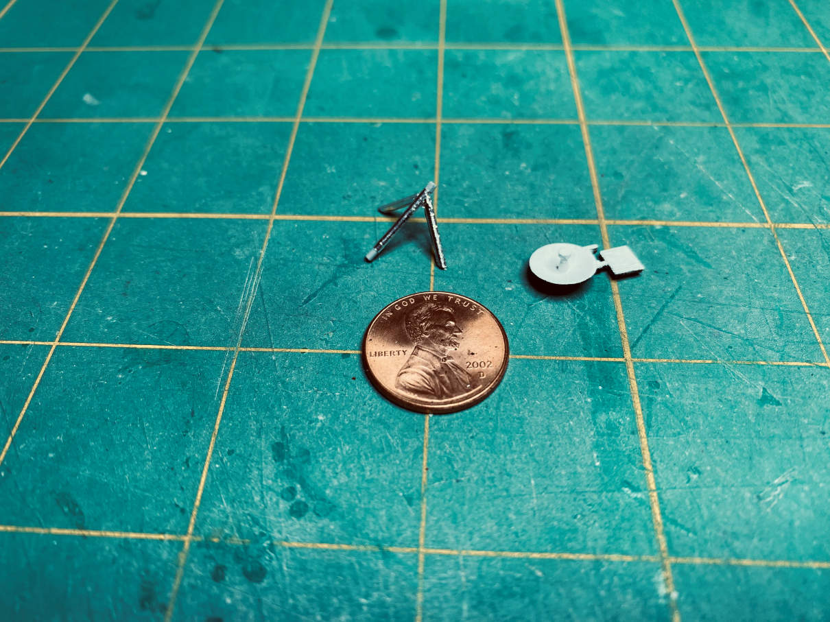
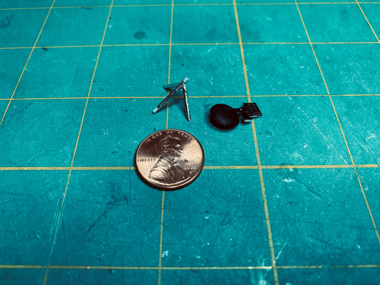
I started with the steerable S-band antenna. Looking at my reference photos I noticed that the main post for the antenna projected more from the side of LM and not the top. The Dragon parts are made for a top mount. So I filled the hole in the top of the LM with putty and allowed it to dry. The New-Ware replacement parts for the steerable S-band can be seen in the below photo, which also shows the filled mounting hole. The replacement parts are much more accurate.

The Dragon part for the antenna support is just barely in above picture on the right. I will lengthen the main support post so it will fit into a new hole that I will drill into the side of the LM.
I moved over to the descent stage and sprayed it black and gave it a matte overcoat. I then started the process of adding the details to it. It will be a combination of paint and Bare-Metal foil. The first area to get the bright aluminum foil was the top center.
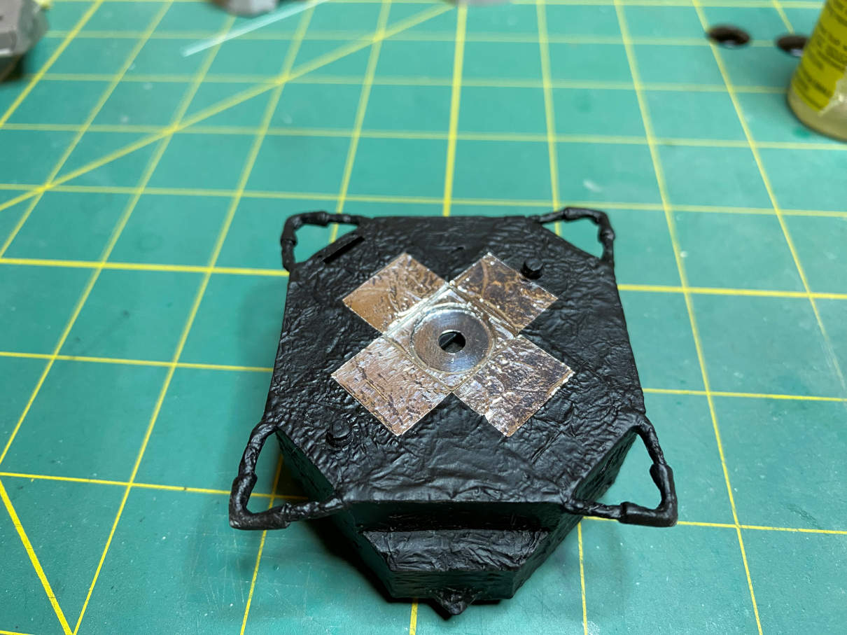
There is more to do with the top but since I had the bright aluminum out I did the bottom of the descent stage. Apollo 10 had a very unique pattern. Thanks to the Paul Fjeld website and Mike Mackowski’s SIM 7.1 for the marking guides for Apollo 10.
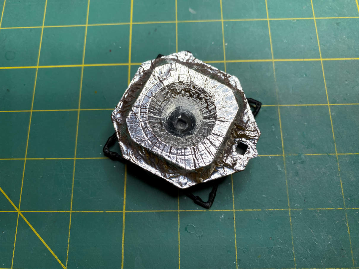
There is more to do. I also have some Bare-Metal Gold foil that will be used. I will also be painting some of the Bare-Metal foil with Tamiya transparent yellow, orange, and red to get the shades I need.
Next, I worked on some of the detail parts on the LM. Beginning with the VHF antennas.
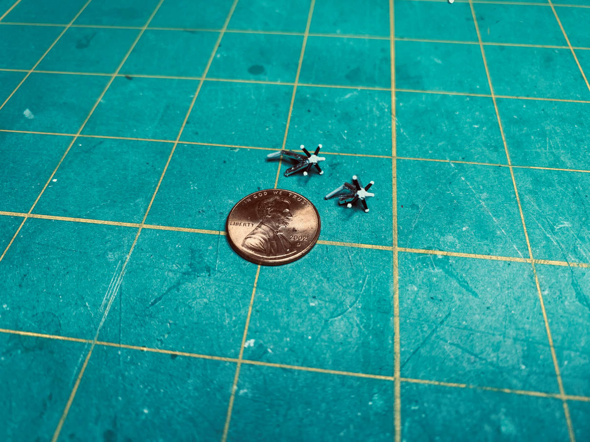
I painted the antennas black and white as they were seen in photos. I then foiled the supports with Bare-Metal foil. I did use some Micro Scale Foil Adhesive to provide a bit of extra ‘stick’ since the foil is a bit on the old side.
Next up was the steerable S-band antenna. After assembling the antenna array, I painted the front side flat white and the back side flat black. I did this after careful examination of my LM photos. The antenna support had previously been lengthened for the new mounting point on the LM. I then foiled it in a similar manner as I did with the VHF antennas. Here is the front side.
This is the back side.
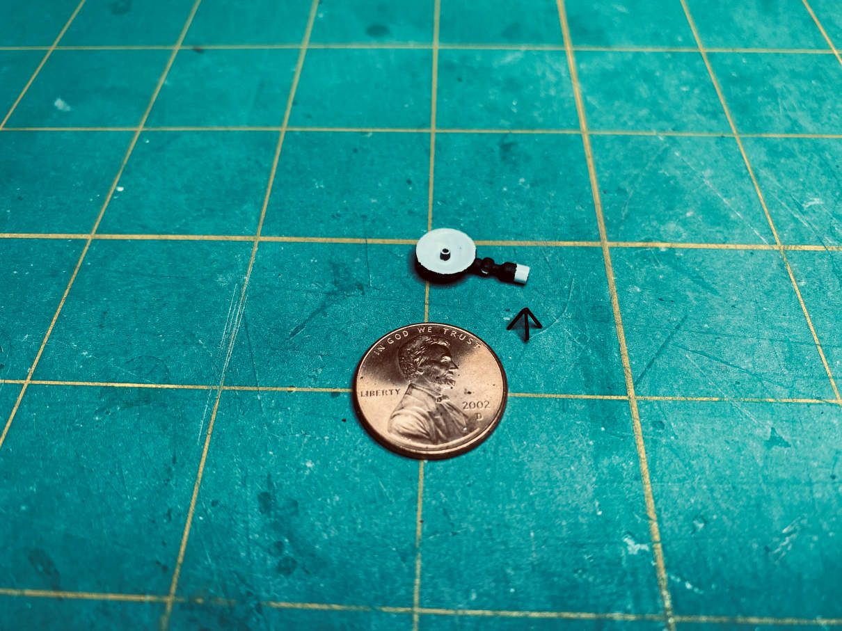
I then started on the rendezvous radar. The dish was not well done. I used my Dremel and removed the very large feed horn in the center of the dish. I then used a small drill and put in four small depressions where the reflector assembly would go. Since I used the New-Ware S-band antenna I was able to cut the feed horn from the Dragon S-band and glue it into the rendezvous radar dish. For the reflector I used four small styrene rods put together with Tenax. I will not glue that in until after the assembly is attached to the LM. Here is a photo of the modified part.
Next up were some more detail parts. The docking target came from the New-Ware detail set. It was primed and then painted flat white. I then carefully painted the black areas with flat black with a small brush and a small amount of paint. To do the black, I placed the two parts on the edge of some masking tape and then, under my magnifier, painted them with a very small brush. On the left of the picture is the New-Ware resin EVA antenna in stowed position. At the top is the landing radar. It was painted with Alclad II chrome over gloss black base. The item next to it is the New-Ware photo-etch landing radar shield.

Lots more to do, but that’s it for now, more to come.
