
The first part will be the Revell Mercury kit. Here is a view of the parts trees.
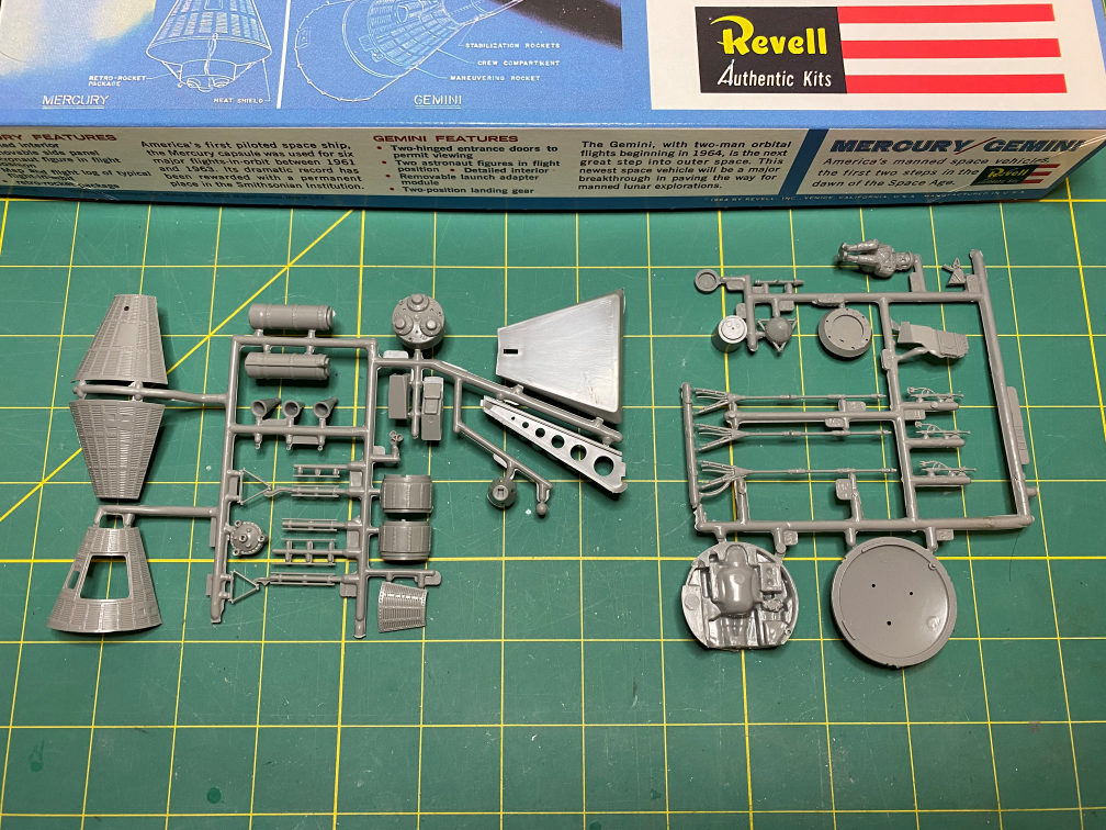
Considering the age of the kit (it came out in the mid 1960’s), the parts are molded pretty well. Not too much flash, but some of the parts aren’t as crisply molded as you might like.
At the end of my previous post, I showed a picture of my model collection back when I was 12 years old. I mentioned that I didn’t have any of those old models anymore. Well, I was going through one of my boxes of broken models (I keep the parts for use in scratch building other items) I found my old Mercury capsule model.

It’s a bit worse for wear. The paint job was not the greatest, but for a 55 year old model built by a 12 year old kid, its not that bad. I may use it for some donor parts if necessary.
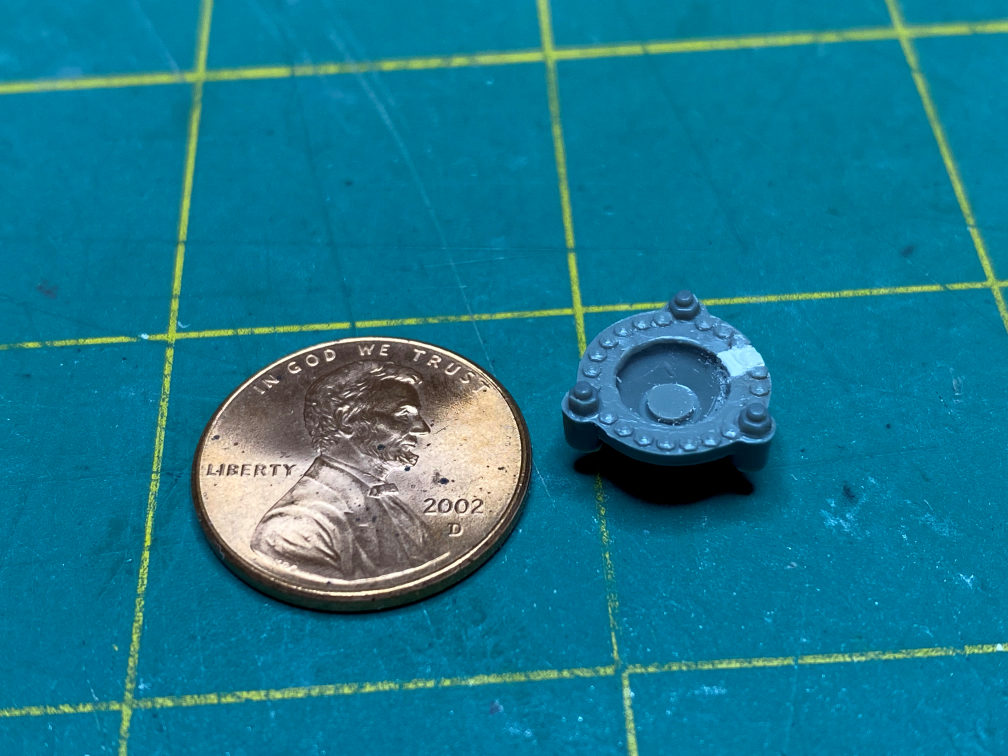
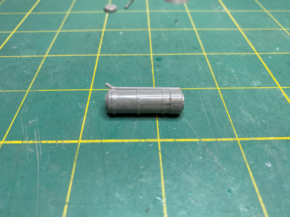
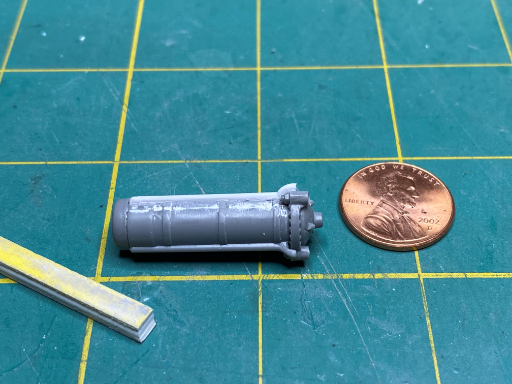
Back to this build, I removed the parts for the rocket portion of the escape tower.
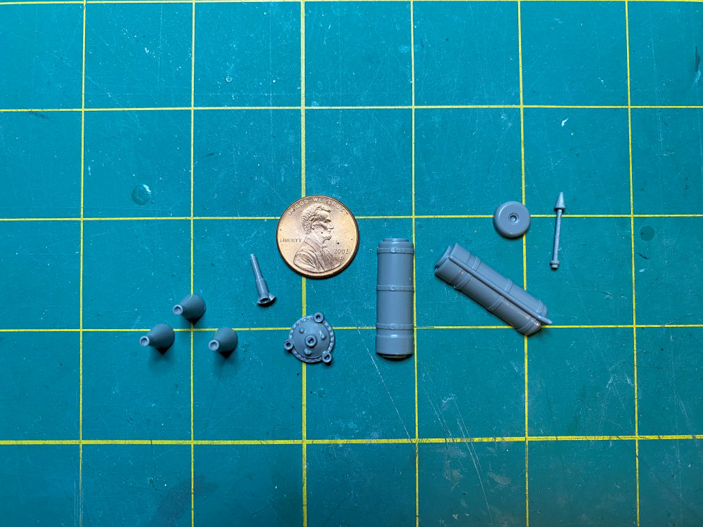
It has some accuracy issues that I’ll fix. First, the wiring conduit on the side of the rocket body is not shaped properly. Also, when assembling it on the base of the rocket (the round part below the penny) the conduit is at the wrong location. Also there should be two of these conduit not just one. So first I’ll fill the slot on the rocket base and fashion a new bolt head at the filled in cut-out.
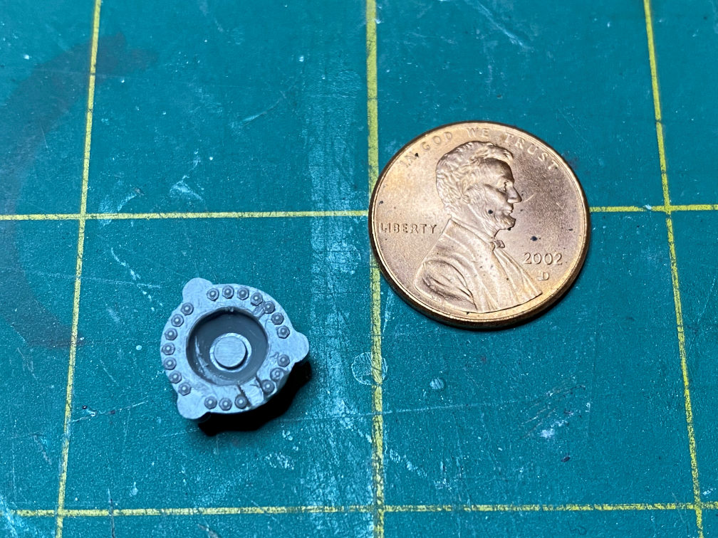
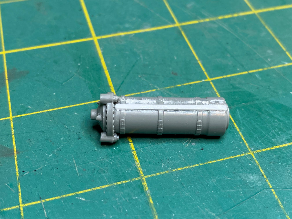
Here is the corrected part.
I added some bolts to the rocket base above the place where the tower legs attach. I got them from a sheet of assorted sizes of bolts and bolt heads from Meng. They have come in handy a few times.
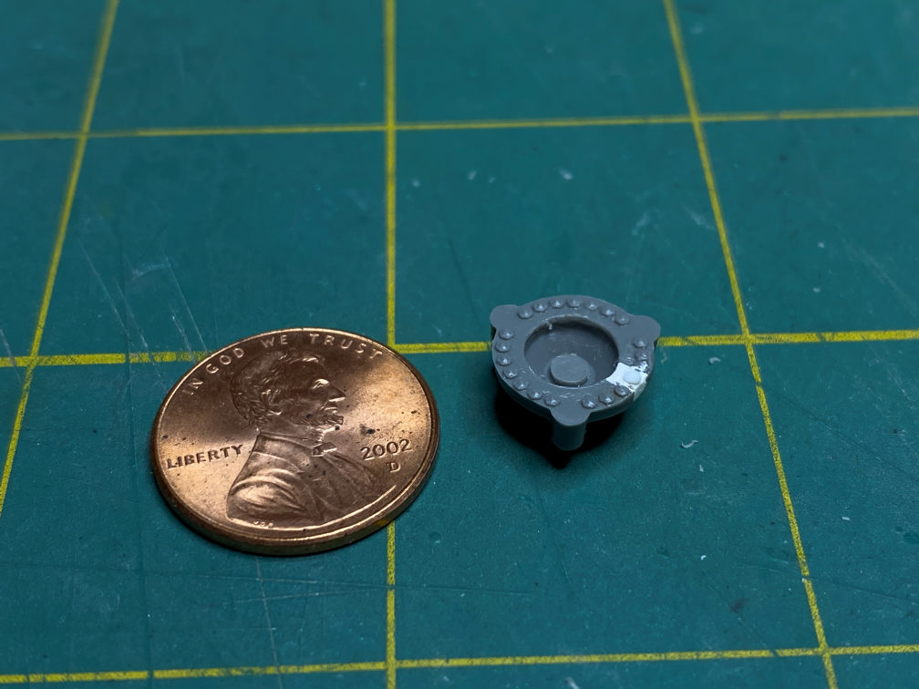
I next carved the bottom of the existing conduit to fit around the base like it should be. The actual conduit is also not the correct shape from the top to the bottom of the rocket body, but I’m not going to fix that on this build.
I’ll also have to clean up the seams on the rocket body, as well as create a second conduit.
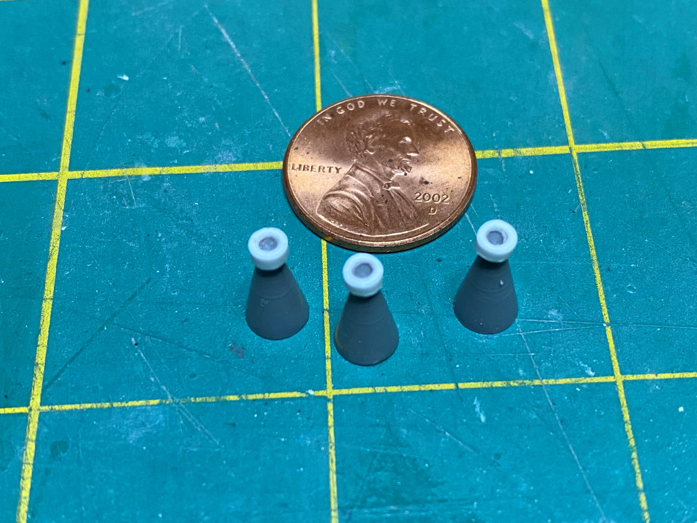
I added a strengthening band around the base of each nozzle, by adding a short section of 1/8 inch plastic tubing.
I started work on the new conduit by locating where the new conduit needed to go. I placed the body on the base with the existing conduit in its proper location. I then marked the rocket body for the location of the new conduit. These two conduits need to be just to the right of where the tower post connects to the base of the rocket. On the real article the conduit carried wires from the top of the rocket to the tower leg where the wires went through the inside of the leg and down to the spacecraft.
I also cut lengths of .020 x .040 strip and .040 half-round to create the new conduit that will fit in the cutouts I made in the straps on the rocket body.

You can see that I also have filled the seams on the rocket body.
I then glued the .020 x .040 strip into the cutouts with some Tenax.
I then glued on the half-round to the strip and took some .040 sheet stock and cut out a rough shape for the part of the conduit that will go over the rocket base and glued it on as well. It was then shaped to match the other conduit.
You can also see that I added the top of the rocket body. It will need some seam work as well.
Next, I removed the tower legs from the tree. In the photo below you can see that I started cleaning up tower leg part 11. This is the leg that is directly in line with the capsule window. The antenna canister shroud is at the top left in the photo. It had some molded in rivets that needed to be removed.
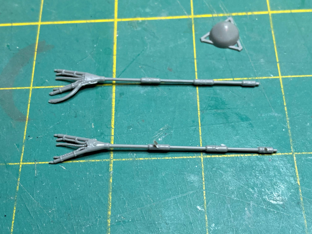
Part 11 will need to have some work done to the wiring at the base of the leg. The large wire curving away from the leg base needs to be removed. On the other leg (part 12) you can see some of the flash and ejector pin holes that need to be removed. Part 12 should not have any wires coming out of it, so I removed them and smoothed the area.
Here is a photo of the cleaned up legs.
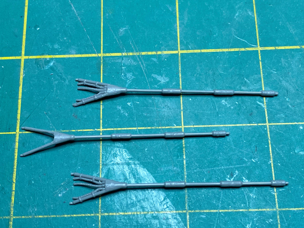
The one on top is part 11. The extra wire has been removed. The second one is part 12 with all of its wiring removed. Part 13 is on the bottom. It only needed to be cleaned up. Parts 11 and 13 will be attached to the rocket body next to each of the conduits. Part 11 is also keyed to the base so that it will line up with the window. The other legs should be attached in sequence counter clockwise when looking down from above the tower. I checked with my references and it appears they will be in their proper positions.
That’s it for now, more work to come.

3 thoughts on “1/48 Mercury Redstone Part 1”