
To begin this update, I glued the instrument panel onto its place on one of the cabin walls. I used a bit of pigment lightly brushed onto the raised areas to add some visibility to the controls.

I then painted some of the details on the cabin back. Most of it was just gray.

I then assembled the cabin walls. They fit fairly well with only a small bit of work where they join.
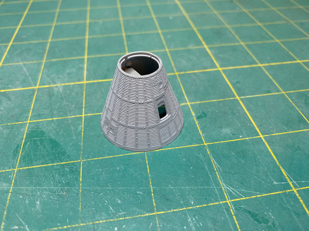
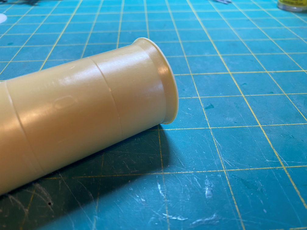
At this point I decided that I’d better check the fit of the capsule on the New-Ware instrument unit. There is a flat protrusion on the end of the adapter that represents the retention ring. That was the ring that held the capsule to the booster during flight. It appeared too thick and too wide. I think this is mainly because of a small scale difference between the Revell Mercury capsule and the Glencoe Jupiter-C rocket. During my research on this build I found that the Revell kit is correct for 1/48 scale. However, the Jupiter-C is just slightly larger than 1/48. This shouldn’t be a big deal and I think I can acceptably make some modification to make it work. Here is a photo of the New-Ware instrument section after I sanded down the adapter area.
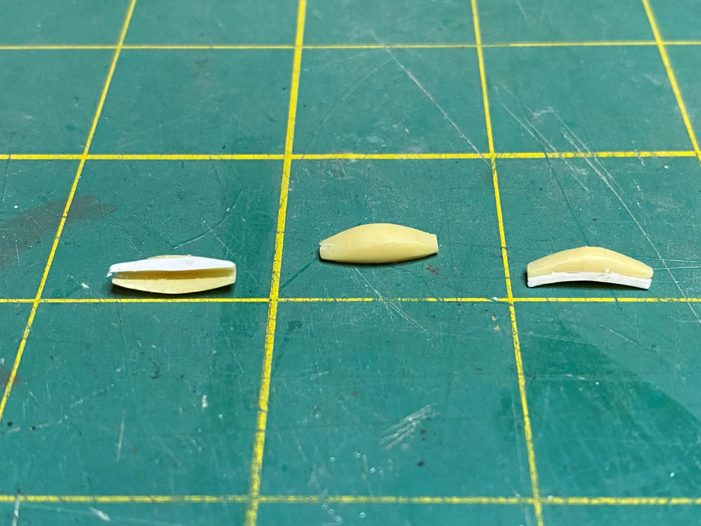
Here is a photo of the three umbilical covers that are around the adapter/capsule joint. You can see a square shape on them. It was on MR-3, but not on MR-4. I’ll have to remove that detail.

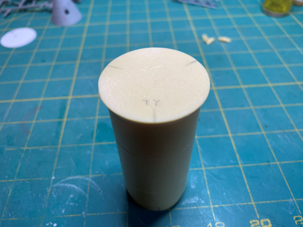
I noticed a funny thing about the axis designations for the Redstone vehicle. The David Weeks drawings that I have for the Mercury-Redstone show four locations around the booster, designated TY, BY, RX and LX. For some reason I never made the connection until now. They are marking the X and Y axis around the booster (that part I got). TY is top Y axis. BY is bottom Y axis. RX and LX are right and left X axis marks respectively. They seem to line up with the capsule window which is also where the astronaut’s head is. So from this point of view his head is at the TY (top Y) and feet at the BY (bottom Y). Of course, then LX and RX line up with the astronauts left and right sides. Seems simple. I don’t know why I didn’t pick up on that before. Anyway, I marked the positions of each umbilical cover for later use. The cover that lines up with the capsule window is attached at the line marked TY.
I test fitted them along with the capsule and found that they won’t quite touch the capsule because of the scale difference. So I glued a section of .030 x .040 strip stock to pad the difference. I then sanded the extensions to match the umbilical cover curves.
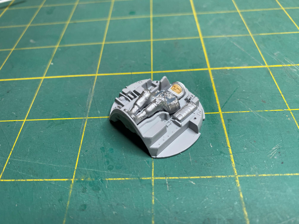
I went ahead and painted the astronaut figure and glued him into his couch in preparation for gluing it into the capsule.
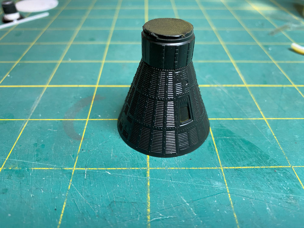
At this point I glued the recovery section to the rest of the capsule. I then painted it Tamiya TS-63 NATO Black. I masked the window opening from the inside and also masked the open top of the recovery section to keep any stray paint from getting inside.
I also took the time to check on my added corrugations on the filled hole. It looks good. Not that noticeable.

I then did another test fit to the instrument unit. I think it will be a satisfactory fix for the size mismatch.

Here is a view from above.

That’s it for this update. More to come. Hopefully I can get the capsule completed on the next update.
Thanks for looking.
