
I started by gluing the upper two halves, parts 11L and 11R, together. I noticed that they were quite out of round.

I decided to try to round them out with some clamping and a soak in hot water. Here it is all clamped up and ready for its bath.

Well, that didn’t turn out too well. I messed up and my water was too hot and I left it in too long. I ended up making it worse. I considered trying to fix my mistake, but it was quite badly messed up. Instead I went back into the stash and pulled out another Jupiter-C/Explorer I kit and stole those two parts out of one of them. I still have one kit left, so if I go insane and decide to build the Explorer I launcher I can still do that.
I checked these parts and they were slightly out of round as well, but not as bad as the first set. This set also had a twist in them. This was also the case with parts 12L and 12R. This time I used some hand pressure and untwisted them and also rounded them out better. They are still just a bit off, but it is not really noticeable.

Here you can see some of the stress marks that I put in the plastic trying to get them back to round and untwisted.
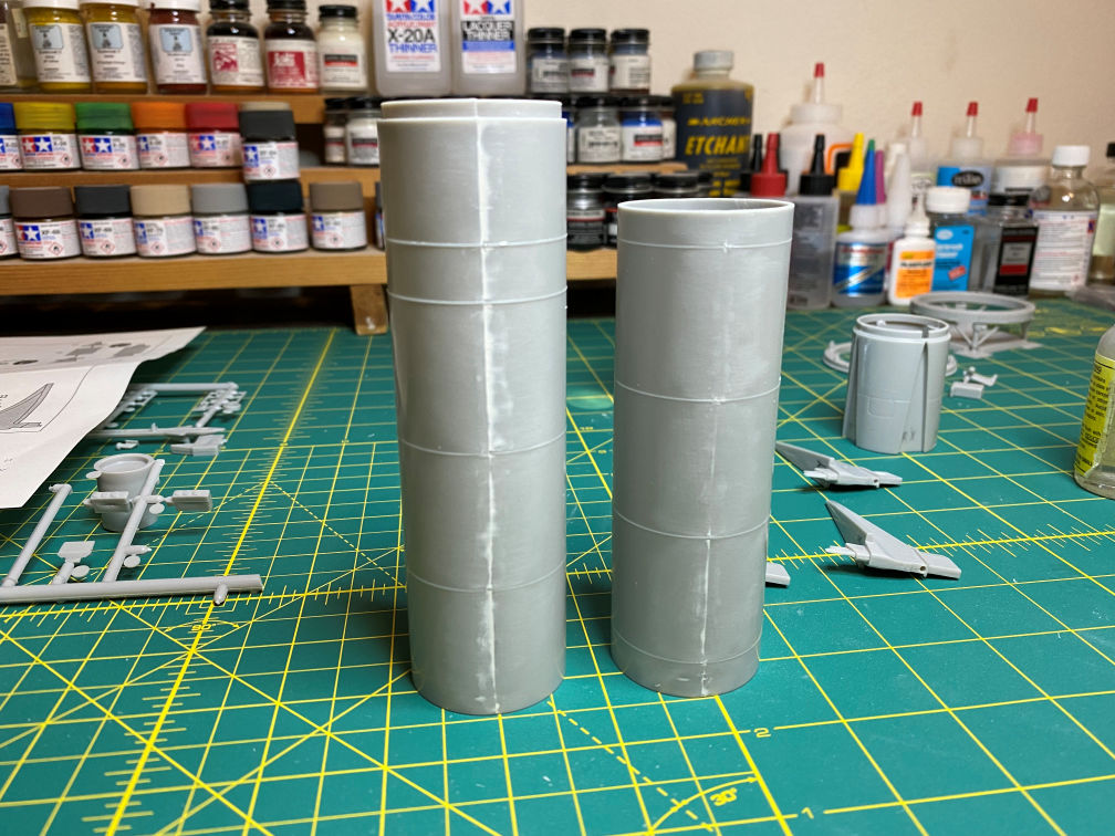
Anyway, with that somewhat conquered, I marked the upper propellant tank section (11L/11R) at the line where I need to cut the Jupiter-C instrument section off to add the Mercury instrument section from New-Ware.

In the background on the left you can see the hopelessly malformed part I had to discard.
I also glued the propulsion section parts 13L and 13R together. With that done, I had most of the sections of the rocket assembled.
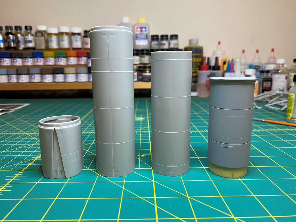
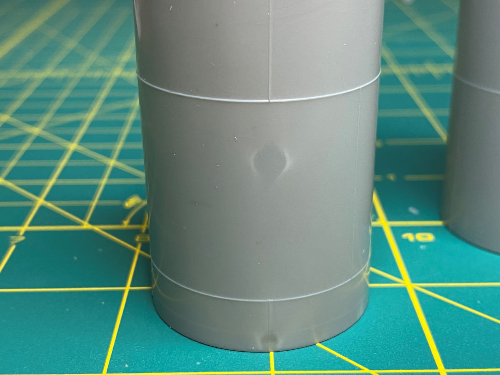
The seam lines will need some work and there are some pretty deep sink marks that will have to be filled.
There is a supposed to be a small gap between the propellant section and the instrument section. To provide that gap I glued a strip of .020x.040 styrene to the base of the instrument section.
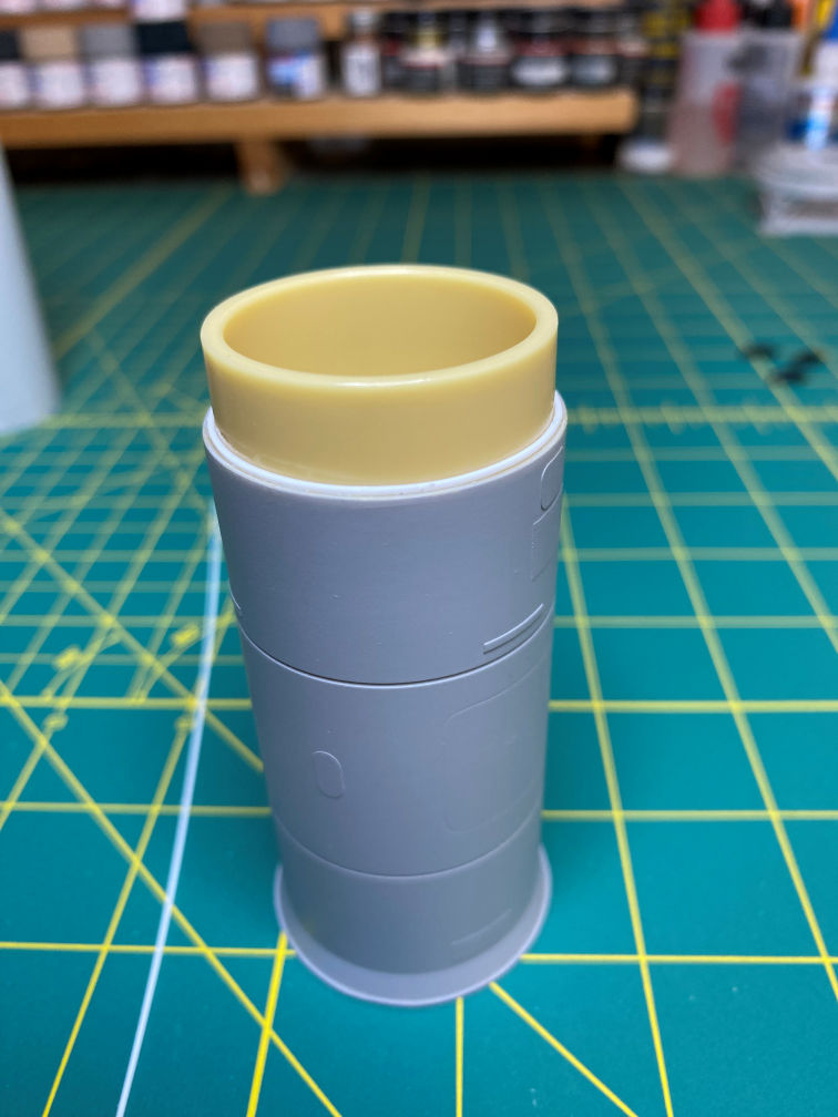
Here is a dry fit showing the small gap that it forms. There is also a gap between the propulsion and propellant section that is molded into the kit part.
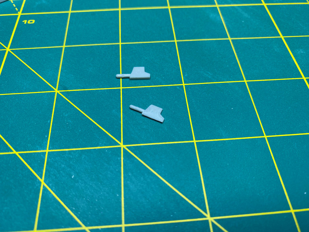
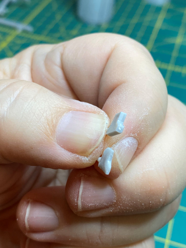
Next I glued the fins together. Then I filled the ejector pin marks on the aerodynamic guide fins (parts 22). I also started shaping the carbon guide vanes (parts 23). The guide fins and guide vanes were not attached to the fins as it shows in the instructions. These will be glued to the fins later on in the build. To facilitate that I had to remove the small band around the shaft of those parts. This should make painting that section a bit easier.

Here is another look at the the carbon guide vanes that are being shaped. The kit vanes are very blocky and don’t represent the actual vanes very well in my opinion.
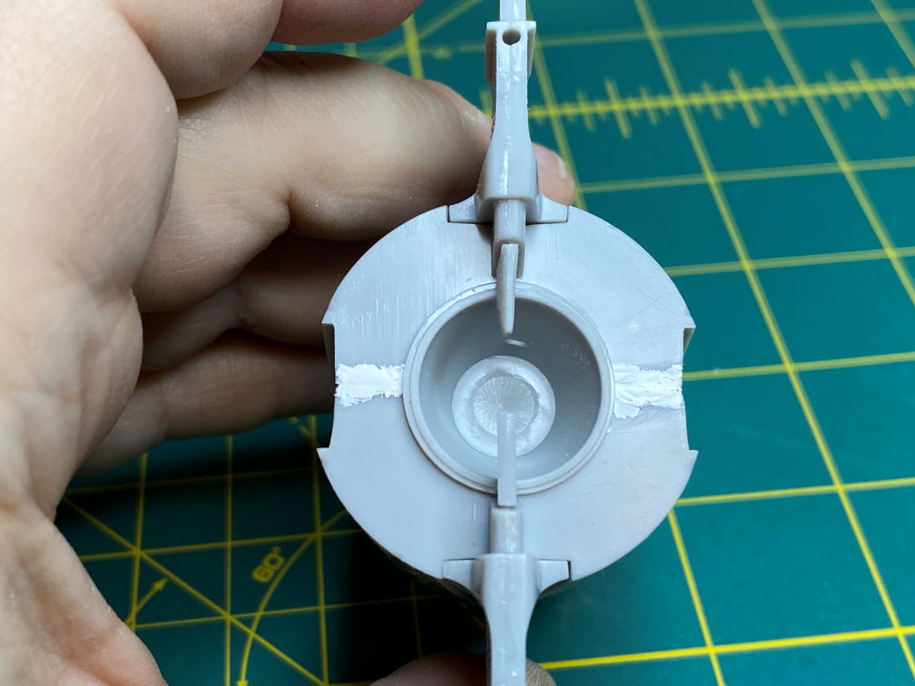
In the third picture you can see some of the propulsion section parts test fitted. The fin on the bottom has not had its guide vane reshaped, the one above has. The seam line is also being filled.
Next I filled the major sink holes in the propulsion section. After primer, I’m sure I’ll find that it needs some more filler.
Here is a view of the bottom of the propulsion section after I sanded the filler. The pencil mark shows where I’ll need to add the turbine exhaust tube.

I next sanded the seam line filler on the propellant section. There will be more seam filling when I join those two part together later on.
I’ve been a bit afraid of how top heavy this model will be when it is completed. The New-Ware instrument section is one large chunk of resin and is quite heavy. I really needed to try and lighten it. I started by drilling some holes in the resin.

I then took my Dremel tool and ground out most of the inside.

This has made it considerably lighter. I also plan to fill the propulsion section with BB’s and epoxy to add some weight to the bottom.
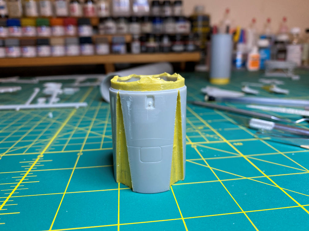
I was looking a the David Weeks drawings that I have for the Mercury Redstone and found some details that I need to add. I started with the hydrogen peroxide fill port on the side of the propulsion section. It consists of a bevel edged depression with a fill port inside that. I started by cutting out the inside part of the beveled depression. Note that the part has also been masked in preparation for priming.

Then I beveled the edges and glued some sheet styrene to the back.

I then glued in a short piece of 3/64 styrene rod.
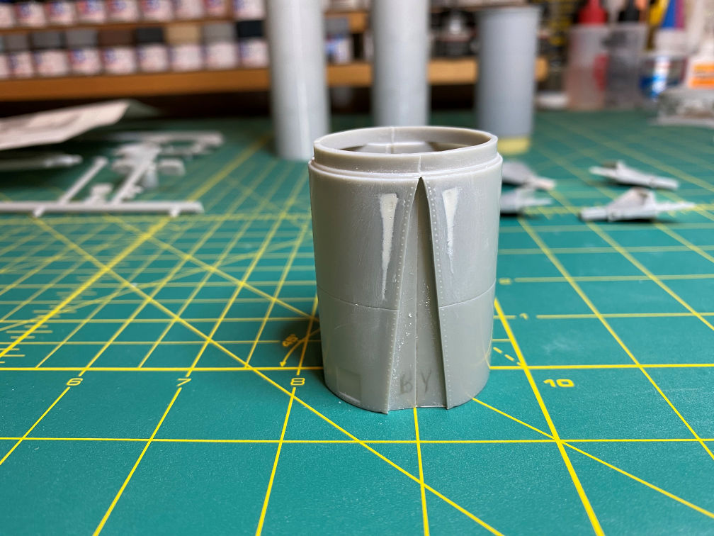
I then glued the two sections of the propellant tanks together and started filling the seam. Here it is after the first session of sanding was done.

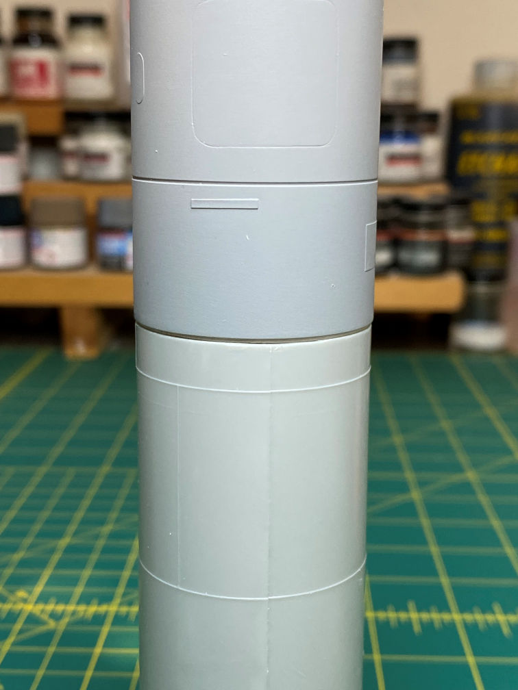
I then marked the location of the three fill, drain and vent ports on the lower part of the propellant section.

Next I created the LOX fill and drain, which was made with a 1/8 tube beveled inside with a 5/64 bit and then a 1/16 rod inside that. The fuel fill and drain was made with some 1/8 tube drilled out with a 3/32 bit then a 1/16 rod inside that. The LOX vent was made with some 1/8 tube with a sheet styrene back.

The LOX fill and drain is on the left, to the right of that is the fuel fill and drain and the one on the far right is the LOX vent. They turned out passable I think.
That’s it for now. This was a productive week. We’ll see how it goes next week.
Thanks for looking.
