

Before starting the main turbopump exhaust I decided to add the enclosure and braces for the fuel fill and drain line. I began by adding a triangular piece on either side of the existing drain line mount point. I made them from .010″ sheet styrene.
I next added a top piece and shaved down the part of the mount that extends past the triangles.
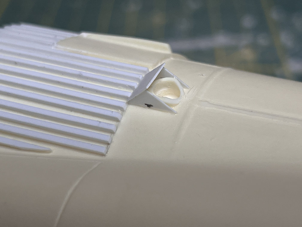
To complete the main housing I added another rectangular piece that covered the mount. I then drilled out a hole so the fuel fill/drain line can pass through.

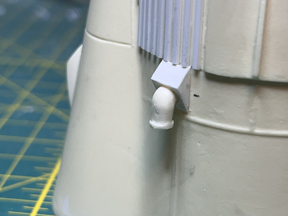
Next the fuel fill/drain line was glued in place.
By the way, a couple of posts back when I was describing adding the stringers to the capsule adapter, I was complaining about a problem with Plastruct styrene strips. Well, it was not Plastruct, it was Evergreen. Both companies make architectural plastic shapes, but it was Evergreen that had the bad 0.020″ square strips. Sorry Plastruct, my bad.
Before adding the final details for the fuel fill/drain line I added a small rectangle with beveled edges that sits a little off the to right. I haven’t found yet what it is for but I added it to match the Weeks drawings.
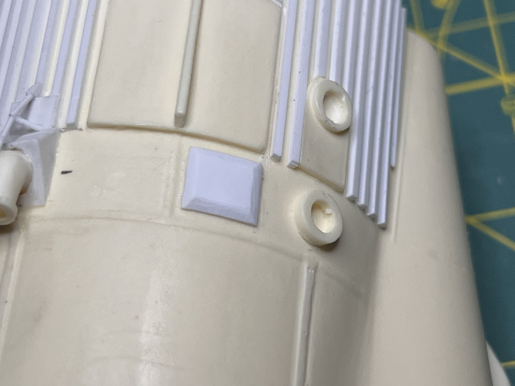
To finish off the addition, I removed a bit of plastic from the top of the three stringers that sit above the housing. Then a square of .010″ sheet was glued in place and I used some Vallejo plastic putty to fill the gaps. Then at the intersection of the new square and the housing I placed an inverted “V” made of .025″ rod. Next I added a small angled bit of .040″ strip just above the square on the center stringer. Then some additional .025″ rod was added from the .040″ strip to the vertex of the “V”. One additional length of .025″ rod was added from the vertex to the bend in the fuel fill/drain fixture. The completed addition can be seen in the two photos below.


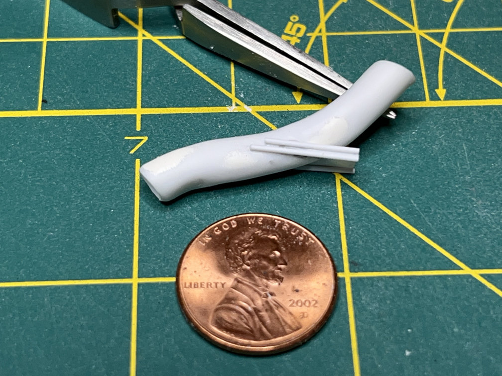
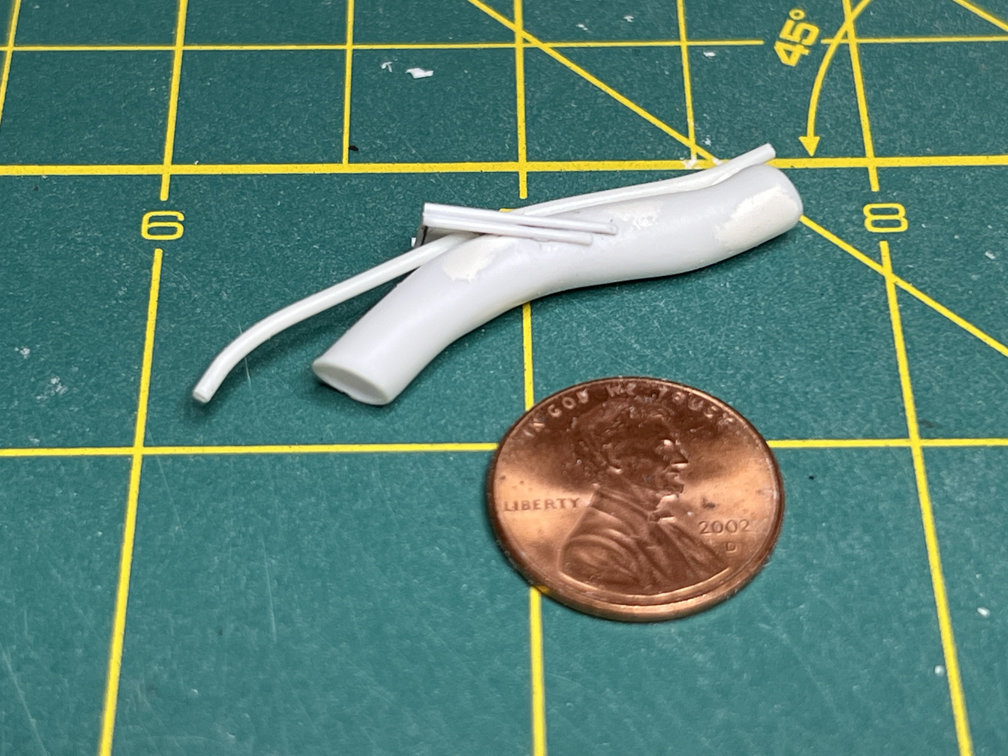
Work then moved on to the main turbopump exhaust port. I started by using heat from an embossing heat gun to soften the 7/32″ styrene tubing and bending it to shape. Here is a photo of the tubing after bending. Next to it is the kit supplied part. You also might just make out some putty on the tubing I made. I created some depressions from the bending process so I filled them in and sanded it back to round.

The next step involved adding a brace to which the main bracing struts attach. I used 0.010″ sheet to make the brace. I attached it with Tenax plastic weld. Here are a couple of photos from different angles. I tried to match the angles shown on the David Weeks drawings.


The next step involved adding some additional bracing to the top and bottom of the 0.010″ brace. I used some 0.025″ rod to make the braces. The ends that attach to the exhaust tube will be slightly rounded later.
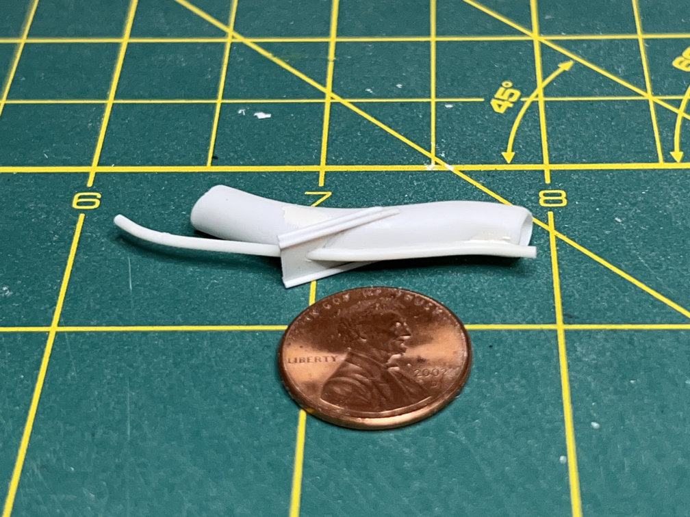
Then I drilled a 3/32″ hole in the solid brace to allow another tube to pass through. Again following the Weeks drawings and some photos, I cut a section of 3/32″ rod that will allow it to run from just past the end of the main tube to a fair amount past the start of the exhaust port. Here are a couple of photos of the new pipe bent and glued into place.
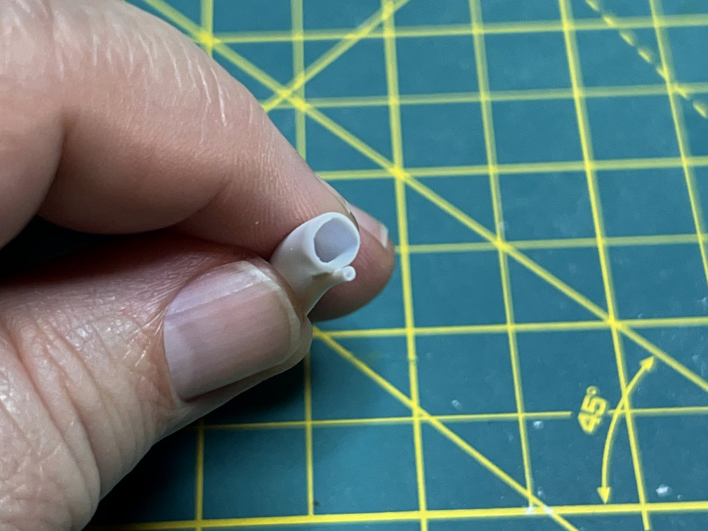
I also drilled out a bit of the small tube on the exit end.
Lastly for this update is a photo of the exhaust port dry fitted to the boat tail with the dry fitted nozzles. I drilled a 3/32″ hole next to the exhaust port to anchor the small tube.
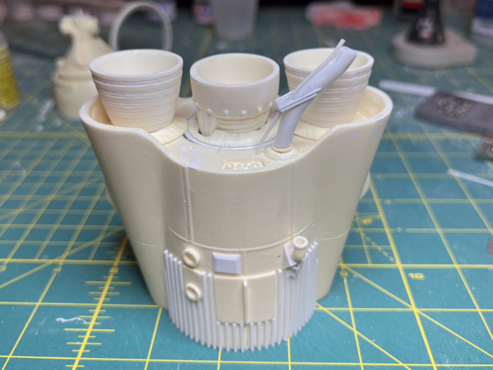
There are other braces that will fit from the bottom of the boat tail to the exhaust tube brace. I’ll add those later.
That’s it for now. That was a task I was dreading. It actually turned out to not be that bad. Thanks for looking and if you’re not subscribed consider clicking the button at the bottom of the page.

2 thoughts on “1/48 Wings Atlas D Update 5”