

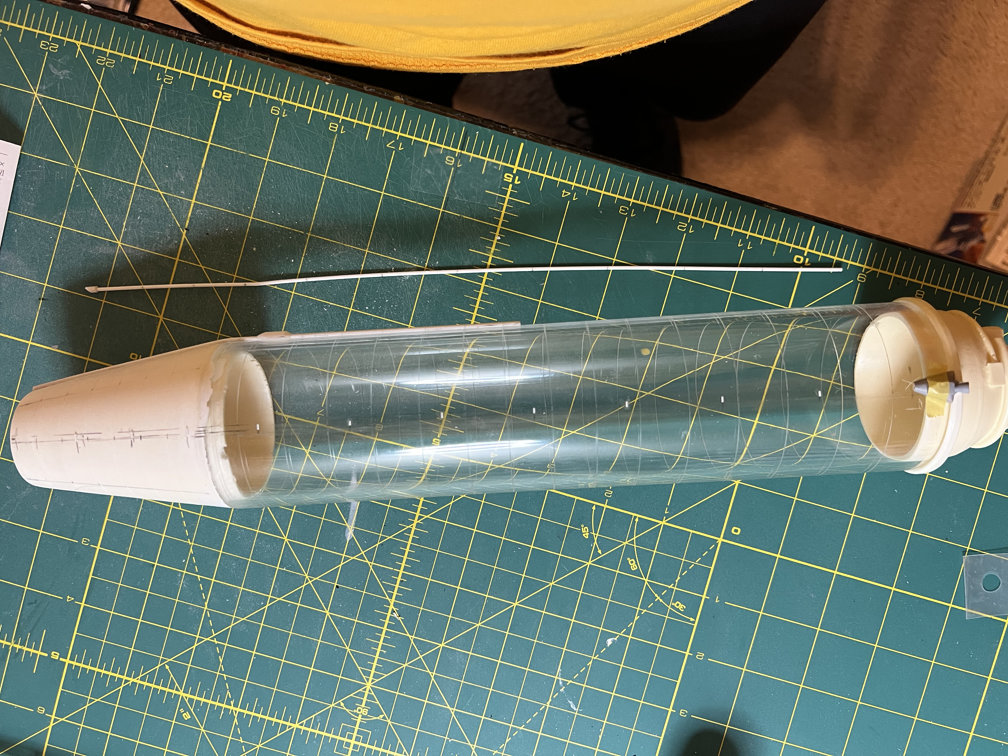
Progress is slow during the holiday season, but I have made some. I’ve been trying for a while now to fin a descent photo of the oxygen tank pressurization line. The line stands above the tank on small stand-offs. In nearly all photo’s you just can’t make out where the stand-offs belong. I finally found one in my large collection of Atlas photos. You can see it above. They appear to be small triangular shapes. I won’t be doing that. Instead I’ll use small sections of 0.030 square strip.
I carefully drew pencil marks where the pressurization line should go. I then used the photo and my 1/16th rod to mark each spot along the rod where a stand off should go. I then used those marks to transfer a where each stand-off should go in the tube. Here is a photo after I attached the 0.030 strips. I used Plasti-ZAP for the stand-offs on the resin part. I used Tenax to attach them to the acrylic tube.
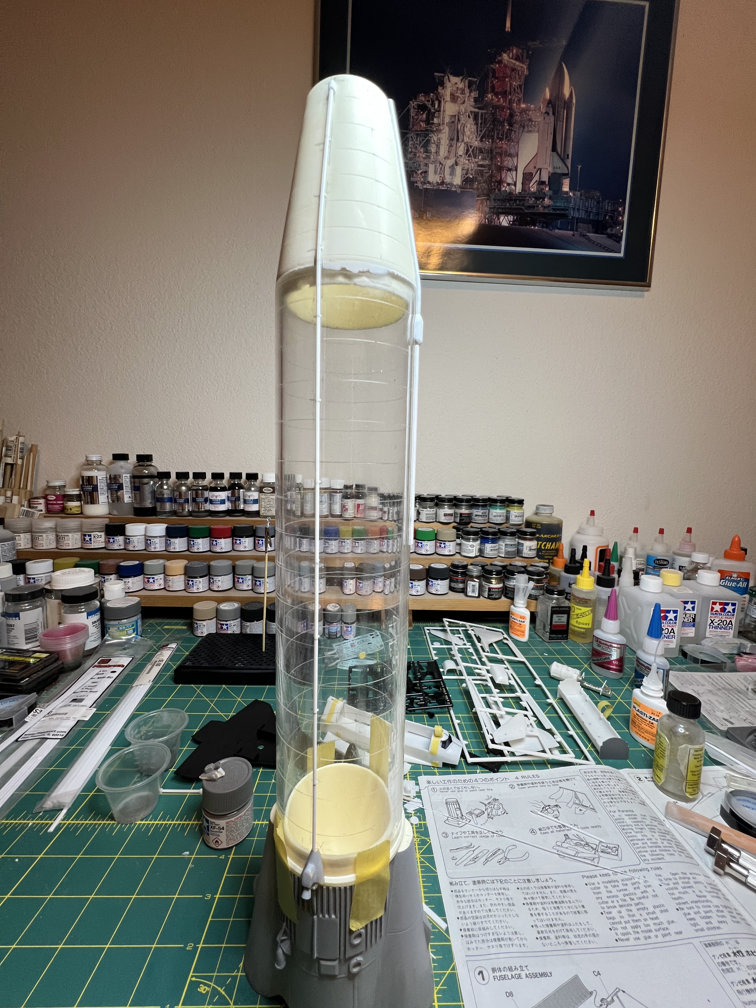
I then carefully glued the 1/16 in rod to the 0.030 stand-offs. Here is a photo showing how that turned out.
Next I glued the short fuel tank pressurization line to the body and the vernier housing. Here is a photo of that.
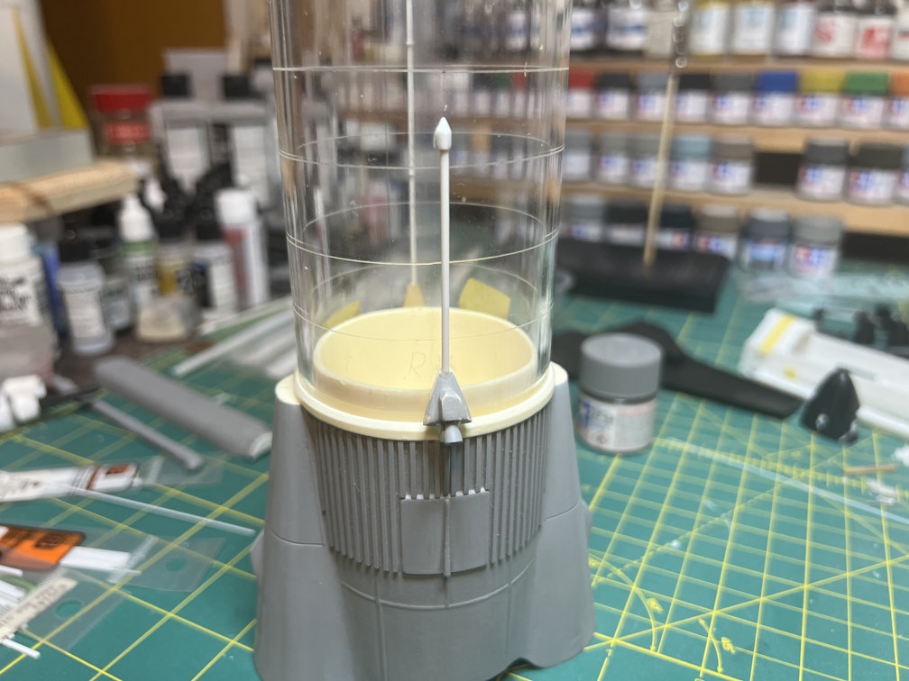
I know the vernier engines are quite off from the proper shape. I made the decision to ignore that and press ahead. I have the drawings that show what they should look like, but that would involve another level of scratch building that I don’t care to take on at this point.
That completes all the parts of the fuel/LOX tanks that need to be attached before paint. Everything above the booster skirt will be Alclad II Stainless Steel after applying a black base coat. The skirt will get painted Alclad II Dull Aluminum. The skirt will then take my attention so I can get the booster engines glued on and holes for the mounting rods drilled.
Thanks for looking.

2 thoughts on “1/48 Wings Atlas D Update 13”