

I was toying with the idea of using some very fine styrene rod to detail the SSME’s that came with the kit. They are pretty plain. Also not quite the right shape, but I thought that if I detailed them it might not be quite as noticeable. Back at the end of March I was on the forum space-modelers@groups.io. A member mentioned that he was building the Airfix 1/144 scale Artemis kit. He indicated that even though the Airfix SSME’s weren’t bad, he couldn’t resist the extra details that were on a 3D printed set from Up Draft Model Works.
I immediately went to the website to check them out. He has 3D prints for 1/72, 1/100 and 1/144 Shuttle RS-25’s and 1/144 Artemis RS-25’s. Unfortunately no 1/200 scale prints. But, he does sell the STL files for the 1/72, 1/100 and 1/144 scale Shuttle RS-25’s. I bought the STL files and also a set of his 1/144 Artemis 3D prints. The prints are beautiful. They are printed inside a cage and placed in a bag and then in a box, to protect them during shipping. The 3D prints are reasonably priced in my opinion, and the STL’s are very reasonably priced. Obviously, you are not allowed to sell any prints you make from these STL’s.
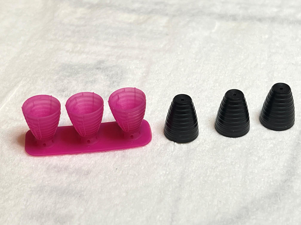
I opened the 1/144 STL file in Lyche Slicer, scaled them down to 1/200 and saved the STL. I opened the STL in Meshmixer and beefed up the minimum thickness. If I had tried to print them as-is I was afraid the smallest piping wouldn’t have printed very well. I sliced the modified STL and printed it on my Elegoo Mars 2 Pro. They printed beautifully as seen below next to the kit nozzles. Excuse the pink resin I had left over from another project.
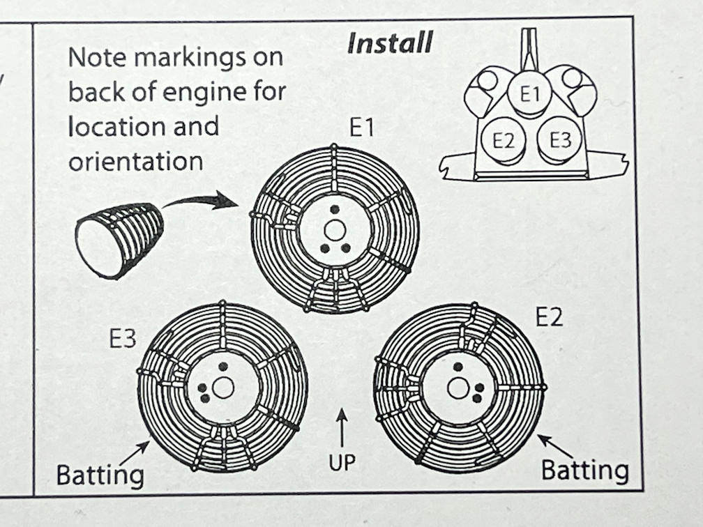
I noticed that on two of the Up Draft Shuttle RS-25’s there is a small section of batting at the end of the nozzle. I really hadn’t noticed the batting in RS-25 photos I have. I went back and looked again and sure enough it’s there. It’s not like the F-1 batting. It is only on one small section at the end of the RS-25 nozzle. He also includes a PDF with the STL and it provides proper engine orientation. That way the batting is in the right place and the engines are rotated properly. That batting is not present on the Artemis version as far as I can tell. Here is the pertinent part of the PDF file.
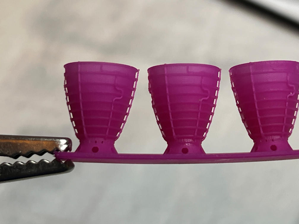
In the photo below showing the three RS-25’s that I printed, you can just make out the batting on the RS-25 on the right. It fills the section between the last two horizontal bands at the end of the nozzle. You can also see how fine some of the detail is. Note the stand-off pipes on the left and right sides of the nozzle.
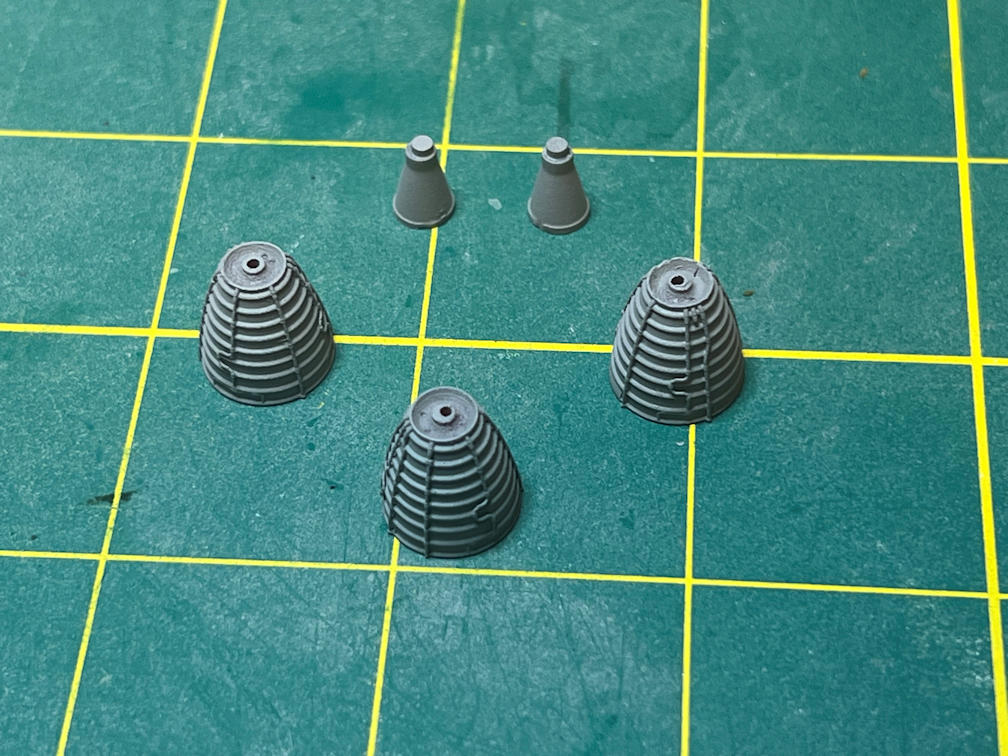
The PDF tells you where to cut the nozzle from the print base. It’s just above the cone shaped section with a hole in it. There are tiny holes at the area where you need to cut. I used a razor saw and removed the three nozzles. Also shown are the conical OAMS nozzles. I wasn’t able to find a suitable substitute in my box of spare nozzles.
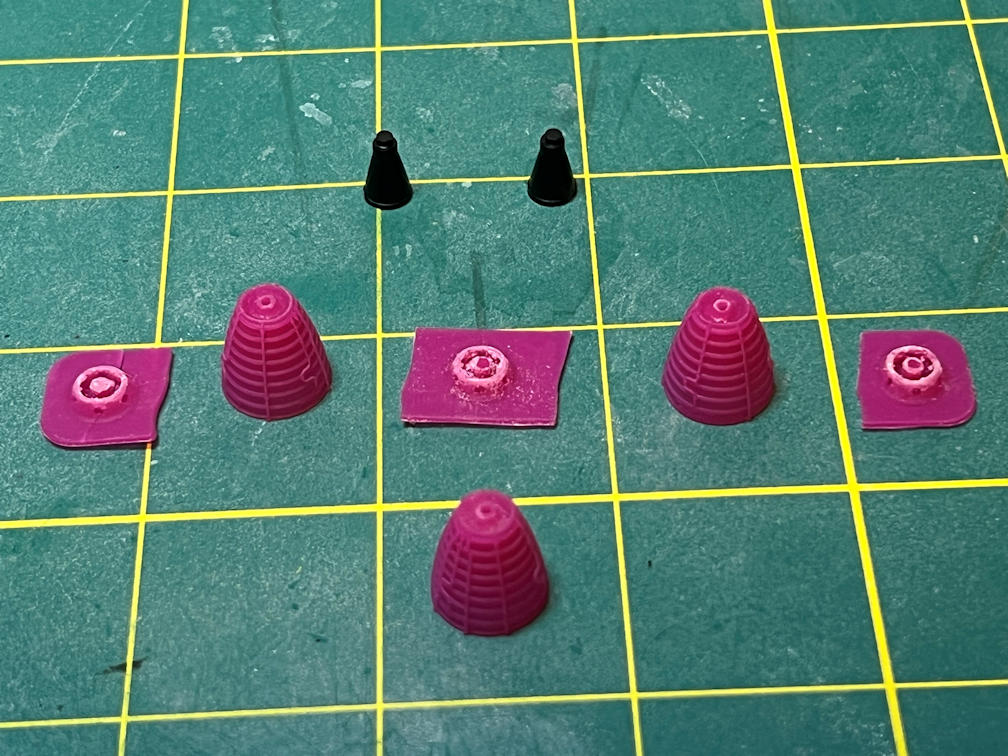
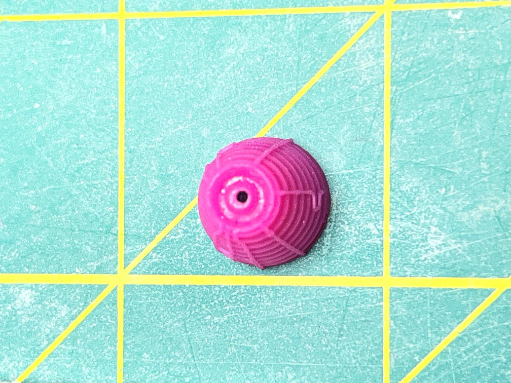
To provide attachment to the shuttle I drilled a 3/64 inch hole in the center of each nozzle. The hole perfectly fits the peg of the Hasegawa kit. Below is a close up. There are supposed to be some small dots inside the back of the nozzle, but they are very hard to see at this scale. They are used for alignment when attaching them to the model. Since I can’t really see the dots I’ll use the batting and the overall diagram included in the PDF to get the orientation right.
After that I primed all the nozzles to get ready to paint them. You can see the details much better after the primer went on.
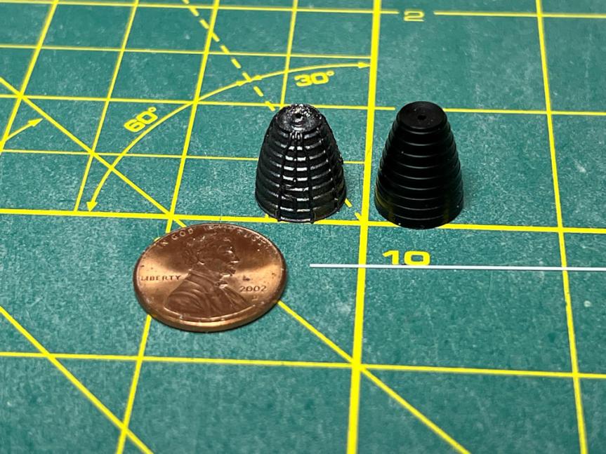
I then painted the nozzles Tamiya Gun Metal on the outside and Tamiya Metallic Gray on the inside. The below photo shows one of the painted nozzles and the Hasegawa original. It also shows a section of 0.015 styrene rod that I was originally going to use to detail the kit nozzles. I like the 3D printed ones much better.
Next I added the payload bay doors to the shuttle. I carefully scraped the paint off the hinge edge of each door and the top edge of the side of the shuttle. I used Plasti-Zap to attach them. It was quite a pain trying to keep them together until the CA set and at the same time not damage the foil on the inside of the doors. I also glued in the Spacelab and experiment pallet.
By the way, remember the hassle I had moving the “NASA” decals on the doors from my last post? Well you can’t see the “NASA” decals on the payload bay at all. But if I had left the decals where I had originally applied them, they would have just barely been visible. So I guess it wasn’t a complete waste of time.
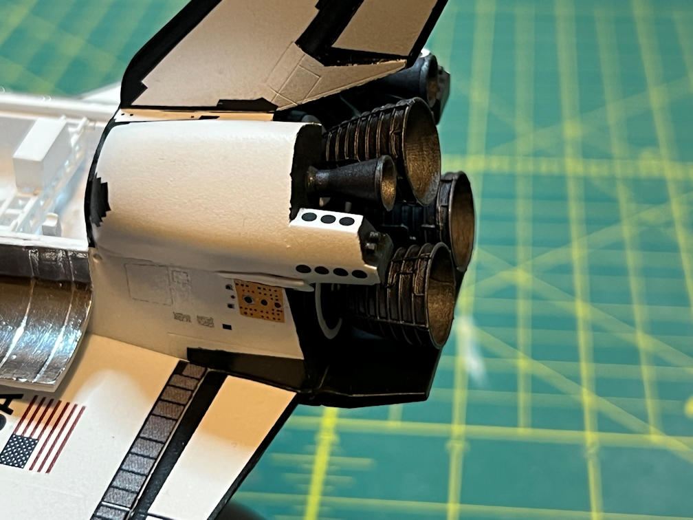
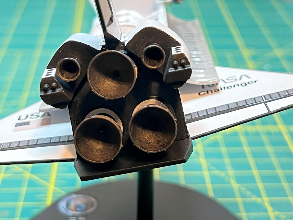
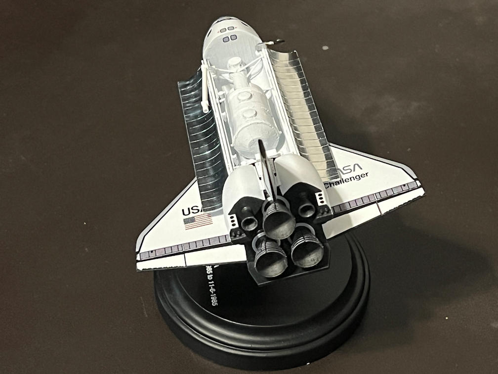
I then attached the engine nozzles with PlastiZap CA cement.
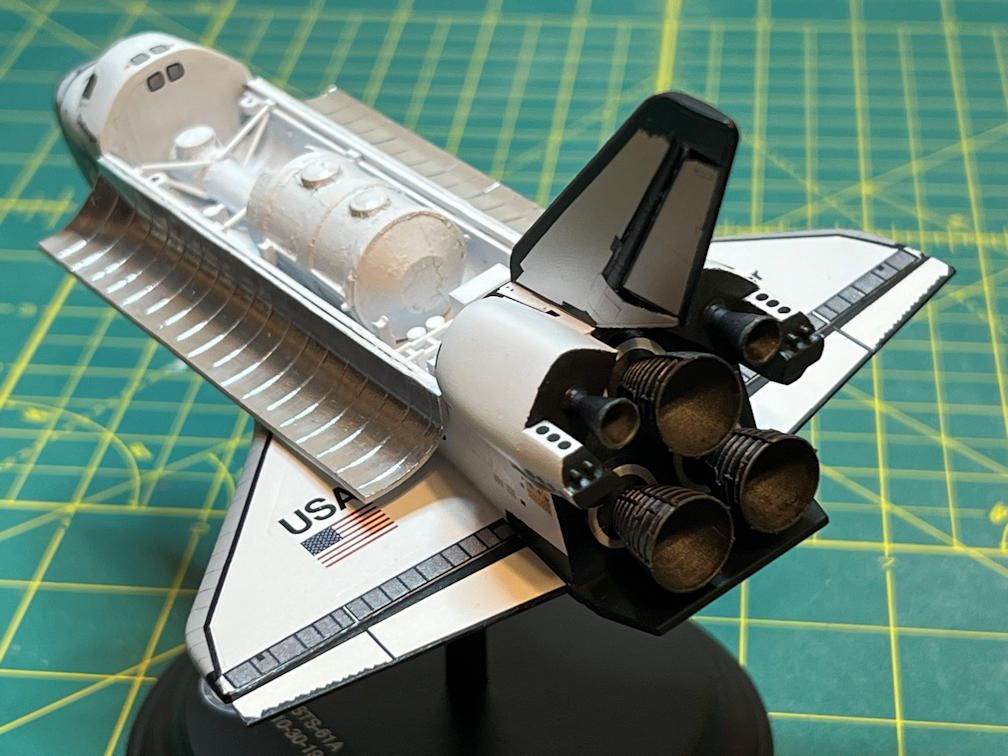
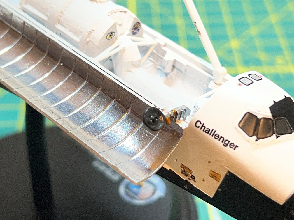
Here are two more views of the nozzles.
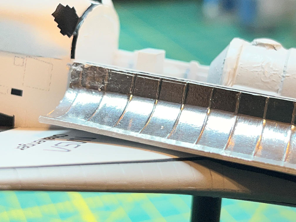
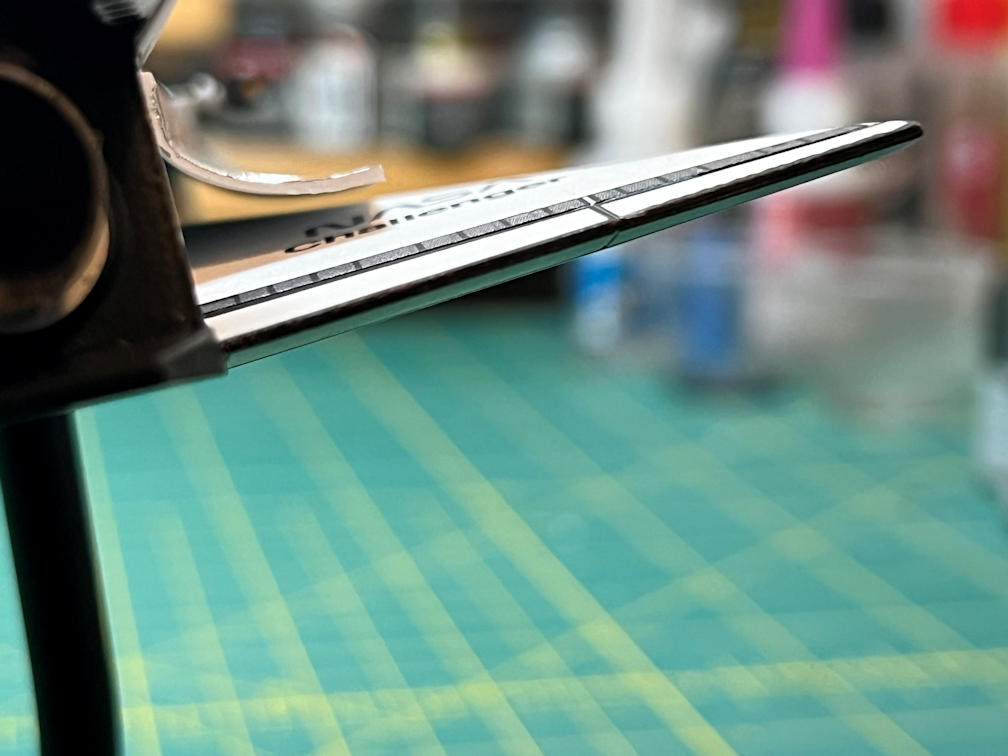
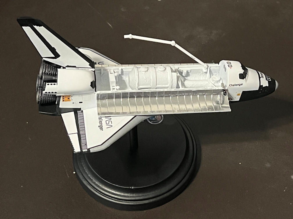
Here are a couple of photos showing how the open payload bay doors are fully open and not touching the wings.
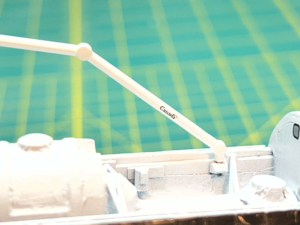
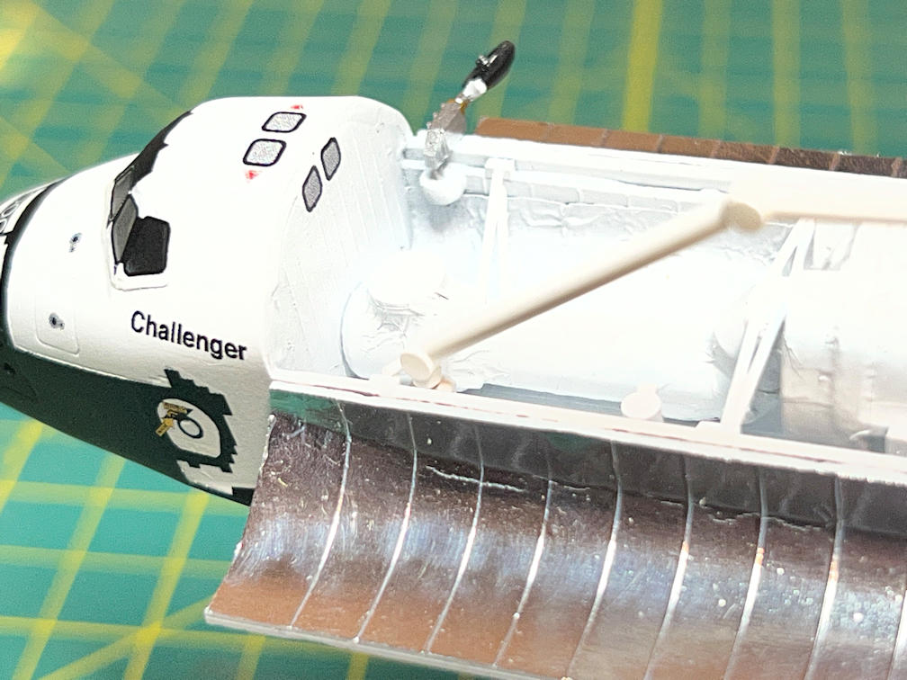
I then added the robot arm and the Ku-band antenna. The second photo shows the tiny Canada logo. I was pleasantly surprised to find the decal was actually readable.
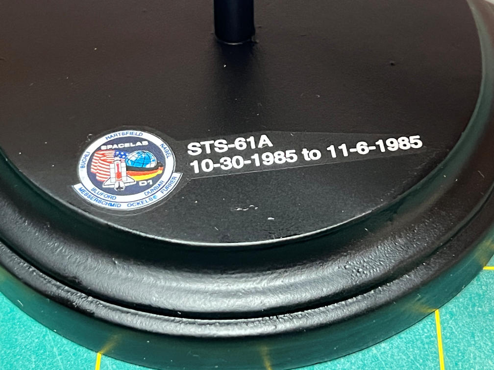
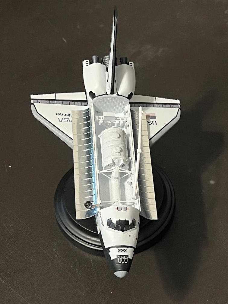
Here is a better closeup of the base. The mission patch came out well, and is readable even at this small size.
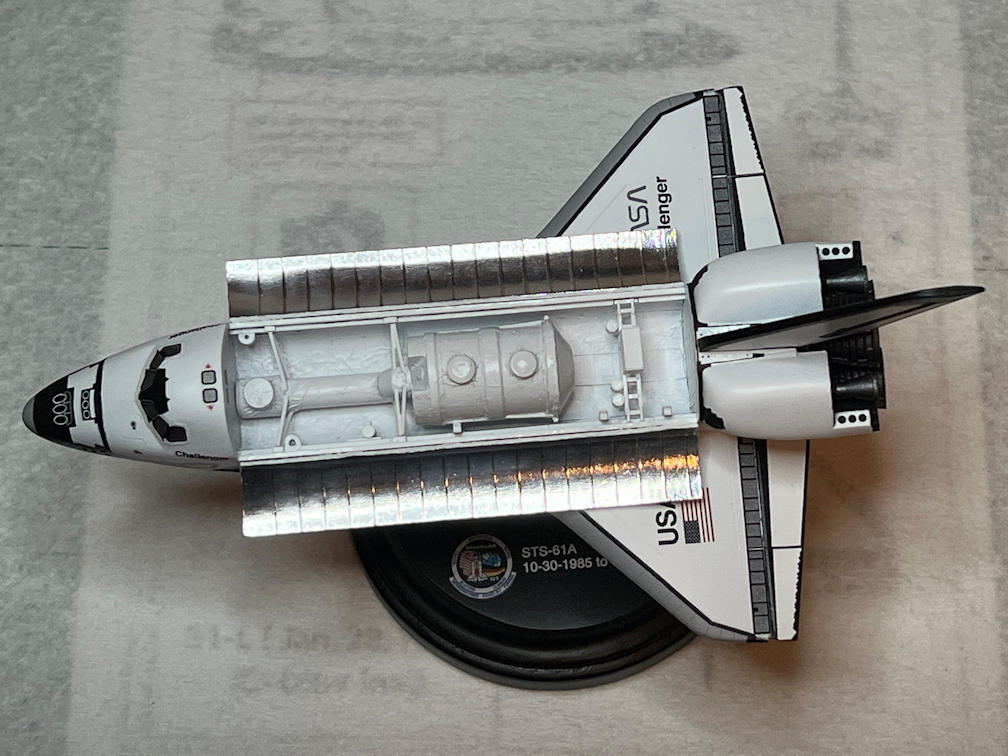
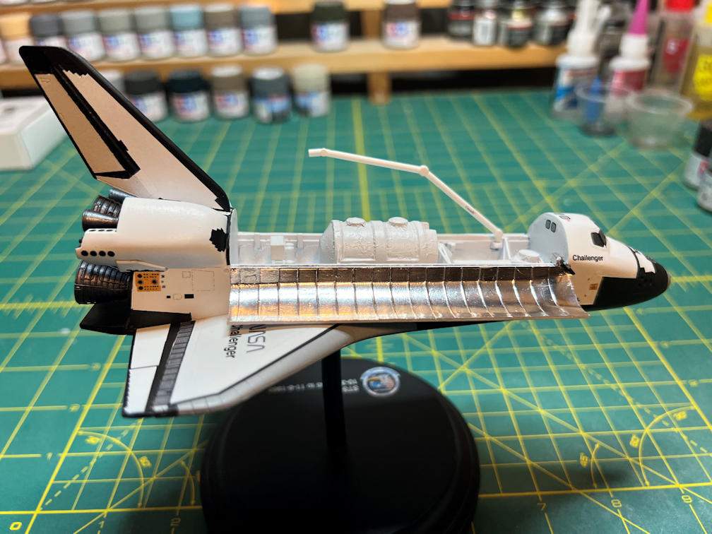
Finally here are some all around photos of the completed model.
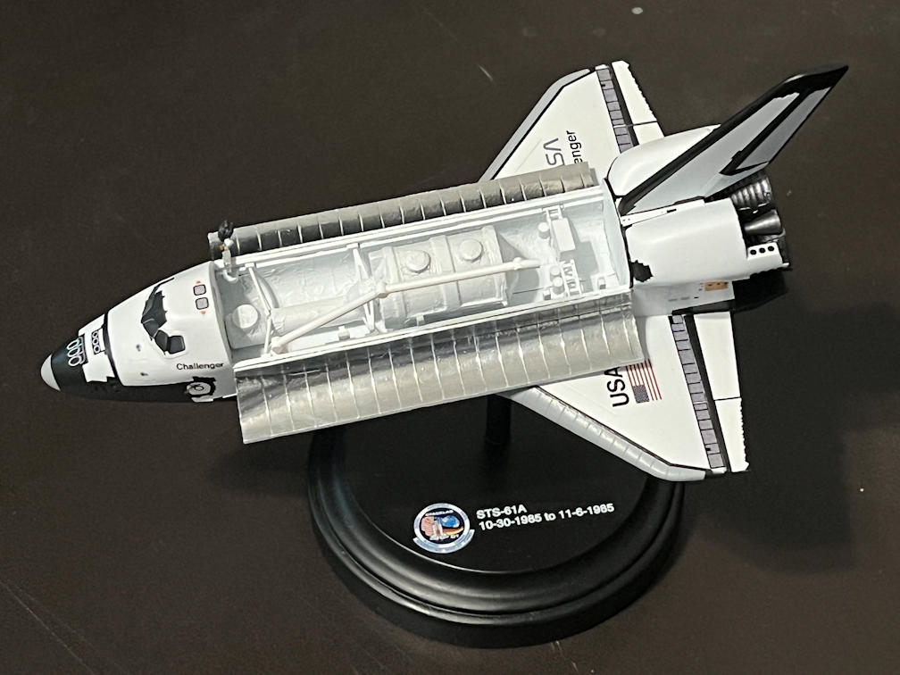
While the Hasegawa kit leaves a lot to be desired, it did build into a nice model. It is quite small. It’s only about 7 inches long. Some of the shapes aren’t quite right but not grossly so. If you build it with the payload bay doors closed you will need to do some surgery since it appears that they don’t quite fit properly. Modeling it with doors open avoided that, but lead to more work inside the payload bay. It is a kit that honestly doesn’t take 5 months to build as long as you don’t have a bunch of interruptions.
Now that the Challenger STS-61A model is finished I can get back to the 1/48 Aurora 7 Mercury capsule. That will complete the Mercury-Atlas build. Thanks for following along.

One thought on “Hasegawa 1/200 Space Shuttle Update 6 (Final)”