
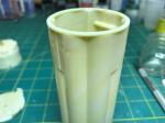
Time for a progress report on the SA-5 build. I started on the aft structure of the first stage. I needed to drill a hole for a brass rod that would attach the model to the display base. I marked an X on the top of the part and put the heat shield on the bottom of the base. I then went to my drill press and drilled a hole through the top down through the heat shield on the bottom. I then inserted a length of brass tube through the top and down into the hole in the heat shield. I only pushed it through until it was flush with the outside of the heat shield. Then I applied epoxy to the portion of the tube sticking out of the top. When that had cured I removed the heat shield and then applied epoxy to the tube from the bottom side. Then I put the heat shield back on. Once that had cured I had a rod that was positively attached to the aft structure and would not move while I added weight. With the head shield removed, I put some BB’s in and then poured in epoxy to secure them. With that I was ready to start adding details to the aft section.


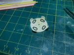
I then glued the halves of the tank section together and then removed the molded in antennas. Next I added some details to the heat shield. I scribed lines into the heat shield to match the pattern of SA-5. I filled four holes for the inboard engines that will not be used. The inboards did not have the turbo pump exhausts around the engine bells like the outboards did. I also added four small bits of styrene rod to represent the water quench disconnects. I then added the flame shields for the outboards by bending some insulated copper wire bent to the correct shape.
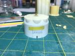
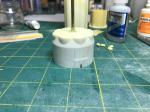
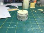
I then went back to the aft structure. I filled the ribbing that was molded in. It is in the wrong place and does not cover enough of the base. I sanded that smooth and applied a light coat of primer to make sure I had them filled properly. I created a pattern to allow me to get the stringers spaced properly. There are fourteen stringers between each fin, with a blank area surrounding each fin. With the pattern secured to the part, I started gluing the .020 x .020 styrene strips in line with my pattern. I had to cut out a bit around where the inboard turbo pump exhaust goes. After adding all the stringers, I sanded a slight taper into the leading edge of them. With that complete I created 8 access doors from .005 styrene sheet and sanded rounded corners into each one. I then made two umbilical doors out of the same .005 sheet styrene. I then marked all round the aft structure for the placement the doors. I glued them on with my Tenax cement.
That’s it for now. Much more work on the first stage to go.
Thanks for looking.
