
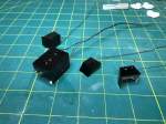
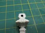
The cockpit light boxes were a bit more difficult than the pod bay. They had to fit around some complicated shapes. This time I made some patterns out of index cards. I then trimmed the patterns until they fix nicely around the cockpit. I then used this as a pattern to cut out the shape in styrene sheet. I then slightly scored the sheet at the fold lines to make bending simpler. The boxes were then glued together with Tenax cement. I then checked them against the cockpit and made whatever final trims were needed to make them fit fairly well. Any small irregularities would be covered up with JB Weld epoxy when they were permanently attached.
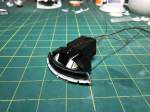

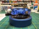
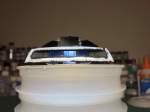
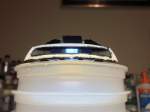
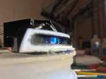
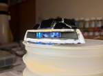
With the light boxes installed, I decided to light them up and see what they looked like. They look pretty good. The photos are a little bluer than what they actually look like. The different colored panels and buttons in the cockpit light up really well. Too bad most of it will be unseen when the whole model is complete.


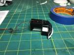
With the lighting complete for now, I moved on to the antenna array. I followed the order of construction for the array, and found out that I should have done more test fitting first. The main antenna went on fine, as well as the cross piece and the spike. But the lower portion of the antenna mount does not fit that well and required some sanding, filling and more sanding. All of that would have been a lot simpler if I had installed those pieces before adding the main antenna. I think what I have done will look OK but it would have been a lot easier if I had done some checking first. (Normally I do, but I got a case of “go fever”.)

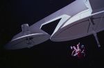
The connector tube that is in the base of the antenna mount required a bit of adjustment to line up with the hole properly on both ends. This tube connects the forward and rear tubes that run the length of the spine. Also in the third picture above, notice the small antennas. I did not use the small spikes in the kit. Instead I cut thin sections of plastic runner and glued them to the center. If you look carefully at the small antennas in the movie, you can see that they do not have spikes. Instead they have flat plates with some small rectangular details on them. At this small scale, I couldn’t get the small rectangles right so I left them as just flat plates.
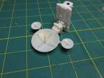
Next I moved on to the back of the command sphere and the reactor/engine section. First I took the back of the command sphere and drilled a hole to allow the wires to pass from the sphere, through the spine back to the reactor section where the batteries and switch will be. I made sure that the hole is not so large that the tube will pass through. I then moved on to the forward neck section. I left it in three pieces to make painting easier.


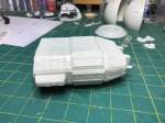


The reactor section also needed modification. In order to get access to the inside where the batteries will be, I needed to lengthen the slots that hold the detail panels. I then applied the detail panels to the top and bottom of the reactor section. The lengthened slots and not gluing the two halves together will allow the top section to be removed and provide access to the inside. I then added the rear neck pieces. Finally, I assembled the three main engines.
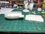
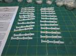
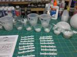
With the main sections complete, the next thing up is the extremely repetitious spine and cargo pods. I’ve got them removed from their runners and organized in numbered cups. I still need to clean up the edges and then start putting them all together. Hopefully I can get them done soon since next week’s weather is favorable for painting.
Thanks for looking.
