
I’ve finally had time to get back to this build. Life has been a bit busy the last month or so. In the brief times I’ve had to work on the model, I’ve tried to tackle the interstage grid. I wasn’t happy with the one that comes in the Apex kit, which has only 8 “V”s. The photoetch one that comes with the RealSpace conversion set wasn’t exactly what I wanted either. I tried using the interstage grid that is in the 3D model that I am using for the upper stage, but after re-scaling to 1/144 it is too fragile and my 3D modeling skills are not yet up to designing my own. For those reasons, I’ve decided that I’m going to go with the photoetch interstage.

It’s not perfect. It is a bit too tall and it has only 9 “V”s where the actual rocket has 12. I did some test fitting and it looks like I can make it work. Sometimes you just have to make a compromise and move on.
I want to pause for a minute here and clarify some comments that I made earlier about the RealSpace Models Soyuz conversion kit. I was a bit critical of the second stage/spacecraft adapter resin part. While it is a bit different from the actual flight hardware, the included details aren’t that bad. In fact, if you’re not afflicted with Advanced Modeling Syndrome like I am, it is a perfectly good conversion kit that will create a model you will be very happy with. Even if you wanted to correct some of the errors it wouldn’t be impossible. There was only one error that is extremely hard to fix and, again, if you don’t have AMS, then you really won’t care. Now I feel better, sorry Glenn, I really do like your kits.
I have attached the interstage to the first stage core.

I then glued a ring of 0.20″ rod around the base of the interstage. This will be for the ring that goes around the top of the first stage instrument section.

I’ve also fabricated the two umbilical connectors that run from the first stage to the second stage. The small gray piece next to them is from the 3D part that I was using for a pattern. The wide part is a stack of four sections of .010x.100 strip stock and then carved to the proper profile. The tails are .020x.060 strip. The long tails will be trimmed and the end lightly rounded before I add them to the model.
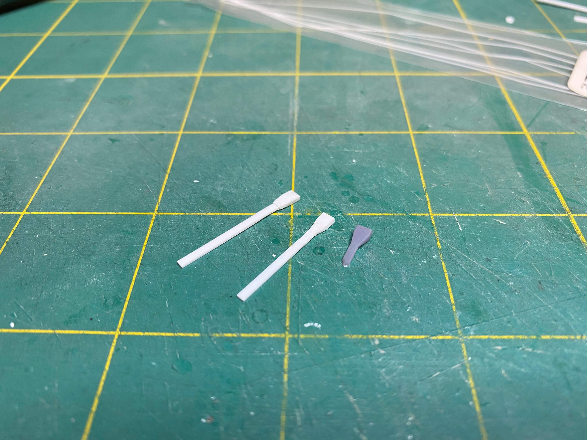
There are also some various boxes that are around the instrument section. The large square is a stack of four .010x.100 strip that is trimmed to a square and then the corners slightly rounded. The slightly smaller bits are .020x.040 strip that is trimmed at an angle to make a wedge type shape. The tiny squares are cut from thin sections of .020x.020 strip stock. The short strips were not used. I decided that they were to large and instead used 3/16″ lengths of .010x.010 strip.

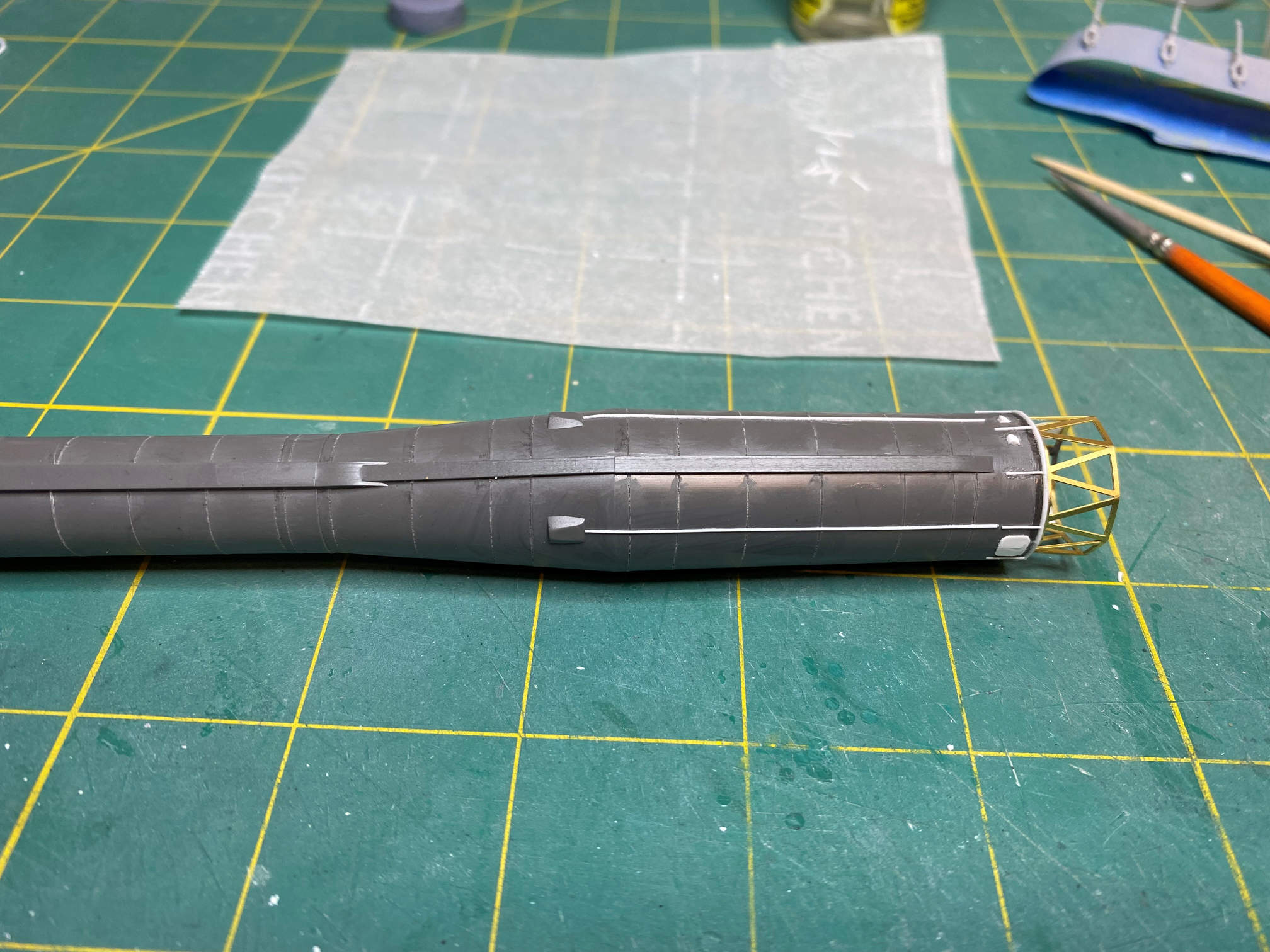
I then added some 0.10″ rod that runs from the booster attach points to the instrument section.

The above picture also shows the umbilical connectors and some of the above mentioned details added. Below is another picture showing this end of the 1st stage from a different rotation.
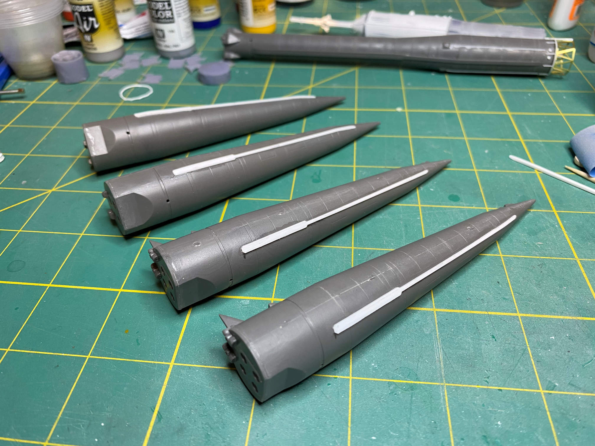
Next was to add a tunnel that runs from near the top of each booster down to near the engine compartment. It is made from a 3 15/32″ strip of .020x.040 stock. I then added a 1″ long section of .020 square stock to each side of one end of the long strip.

Here is a look at the boosters after the tunnels were added.
That gets the main parts ready for priming. That will be next along with the beginning of painting the main parts.
Thanks for looking.
