
After doing three Mercury Redstone models with varying degrees of detailing I decided I wanted to do a fairly easy model for a quick project. I looked through the stash and found the Lindberg Space Base and Satellite Explorer kit. I’m not particularly excited about the Satellite Explorer part of the kit but I did like the Space Base.
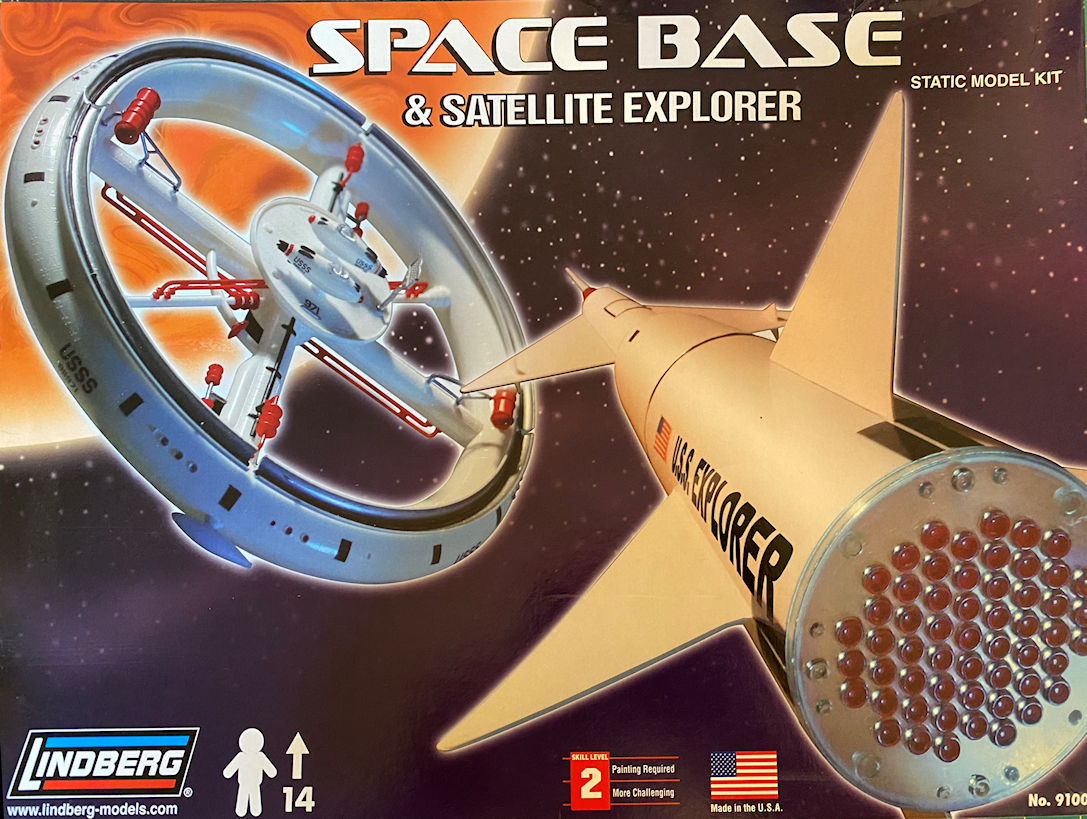
I’ll just do the space station kit and leave the rocket for another time. The Space Base kit originally came out in 1958. In 1959 it was part of a 5 kit set that included the Space Base, Satellite Explorer, Moon Ship, Flying Saucer and a Satellite Rocket. In 1969 the space station by itself was re-released again. This time renamed the Mars Probe Space Station. In 1976 it was re-released as a stand-alone once more. In this re-boxing it was called the Star Probe Space Base. It then disappeared until it was re-released in 2008 along with the Satellite Explorer rocket. This is the incarnation that I bought. The latest re-release was in 2017, this time in the same 5 kit set from 1959.
It is a rather simple kit. It only has a few parts. Considering the molds are 66 years old, the amount of flash isn’t that bad. However, nearly every part shows a misalignment of the mold halves that will make cleaning the parts up for paint and assembly a bit of a pain. Also, at least on my kit, the two station halves have a bit of a nasty warp that will need attention.
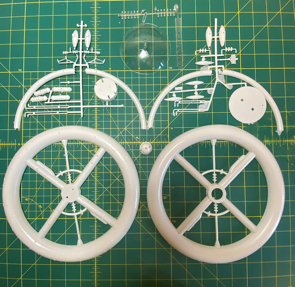
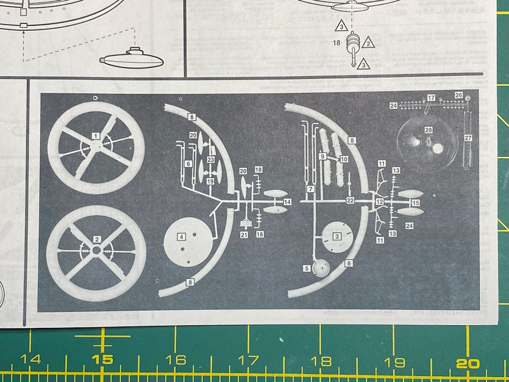
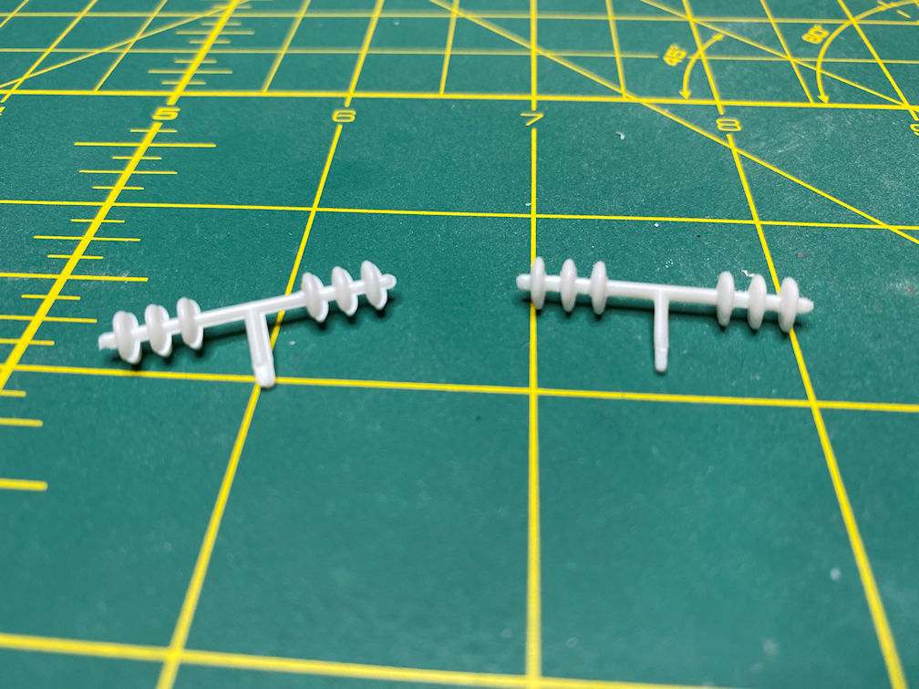
The parts are not numbered on the tree. Instead they include a photo of the sprues with the parts numbered. So you may have to refer to the photo to make sure you have the right part. However, I noted that two parts included in my kit are not in the photo and are not referred to in the instructions. They are the two small parts that fit in the back of the two “space cars” that are built later in the instructions. Those parts represent the “space car exhaust” (rocket nozzles) for the “space cars”.
I’m not going to exactly follow the instruction sequence. This will probably get me in trouble somewhere down the line, but there it is.
My build started with the main station ring halves. Due to the warp, I had to glue the wheel together in small sections at a time. When I got to the warped areas I used masking tape to hold the halves together while the glue set. Here is the top side of the station ring.
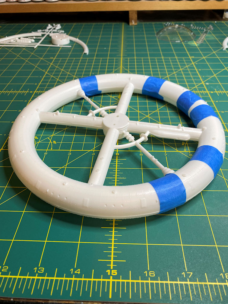
Here is the bottom side.
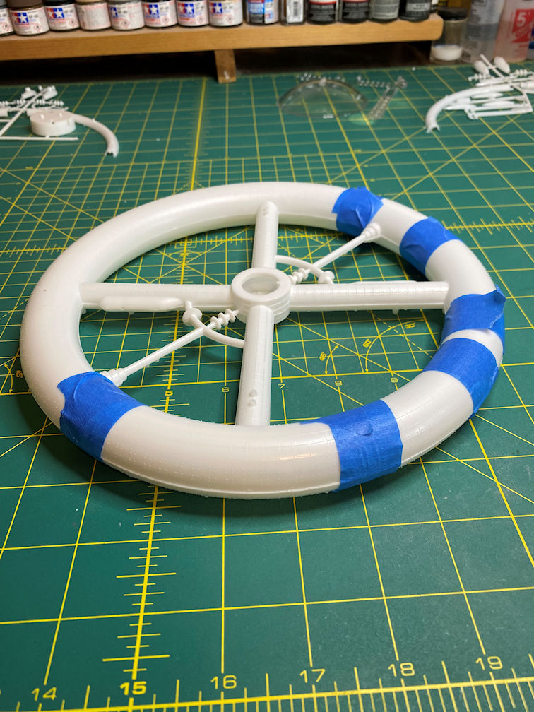
You can see some areas where the two halves don’t quite line up. I’ll have to sand those areas and possibly use some filler. There are a lot of molded in rivets on this kit. Fortunately, due to the molding process, there are no rivets near the seam. That will make smoothing the area much simpler.
The details on the inside of the ring show the mold line mismatch that will have to be cleaned up. Here is a photo showing one side that has been cleaned up and the other half that shows the mismatch.
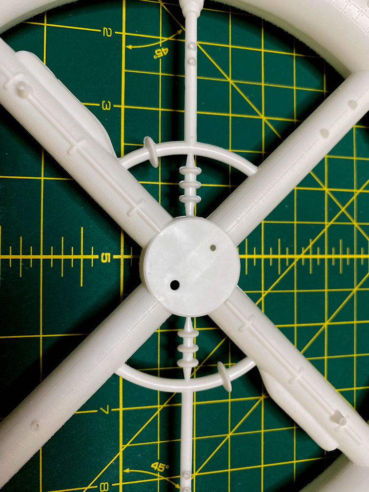
The mismatch looks a bit like flash in the photo but actually the two halves just don’t line up. I did quite a bit of carving with my X-acto knife to clean up the details shown in the lower half of the above photo.
After taking care of the inside the ring, I started smoothing the seams on the outside of the station wheel. Here is a photo of one section after I smoothed it.
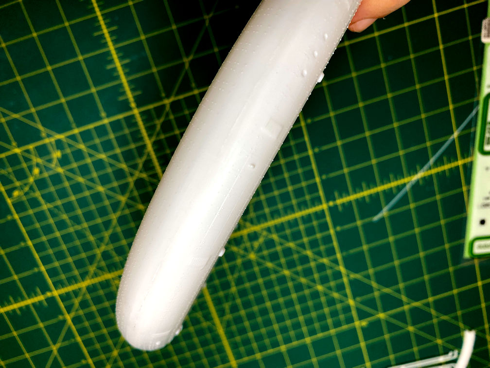
The white plastic doesn’t photograph well. I’ve enhanced the contrast in the above photo to try to bring out the details. You can click on any image and get a larger view.
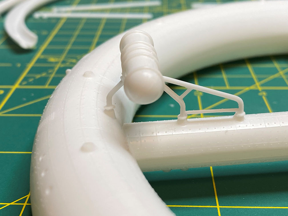
The next part was cleaning up the mercury boilers that line the top of the station in four quadrants. They were meant to provide power for the station. Here are two that have quite a bit of flash.
I started with the below two since they didn’t have as much flash. The one at the bottom hasn’t been cleaned. The upper one shows a complete cleaning.
It’s hard to see but each one has a molded in pipe that runs the length of the reflector.
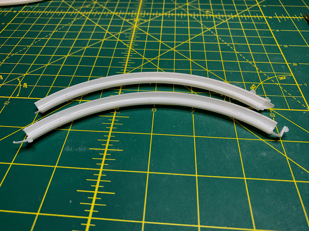
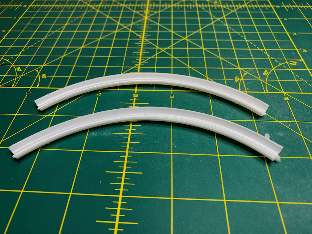
There are four sets of conduit pipes that run along the outside and connect the hub to a spar of the station. They have the same mold mismatch that is a common theme on this kit. The below photo shows one of the sets of pipes that run along the topside of two of the main spars. It does a good job showing how much the parts are misaligned.
Here is a photo showing one cleaned up and one that has not been touched.
The other set of conduits go on the bottom of the station and are very much like the above pips. The main difference is that the pipes are longer.
There are some other parts that called gas condensers. The large circular features were a bit of a challenge to get trimmed up acceptably. The one on the right is cleaned up and the left one has not been touched.
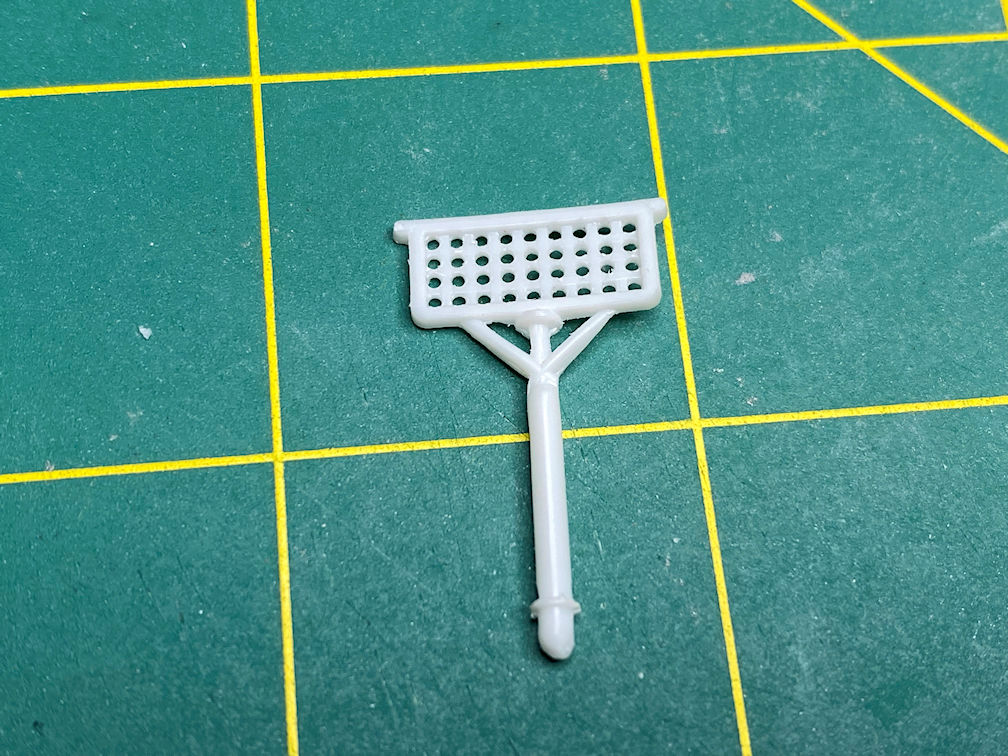
There is a radar antenna that fits on the top side of the station. It had a square grid pattern that was not very consistent. I decided to drill out the squares and make them round and slightly larger.
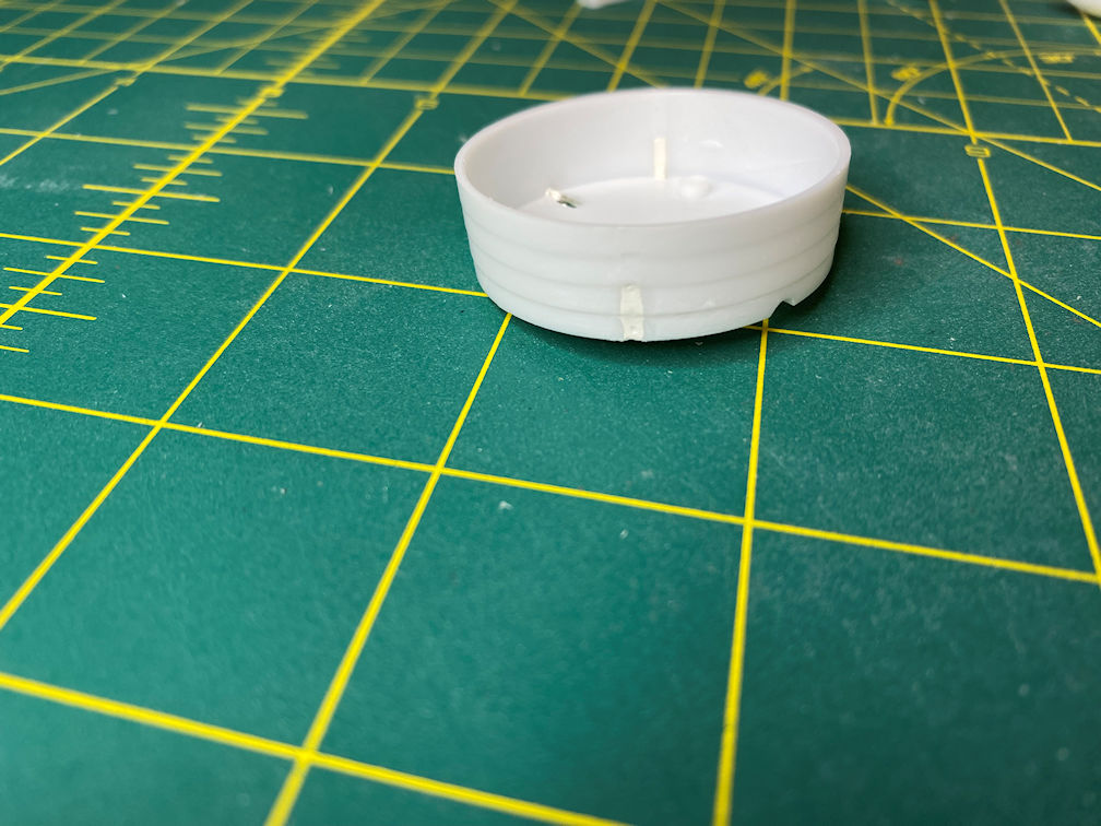
There is a communications dome that goes on the bottom of the station hub. It holds a communications antenna and two sets of conduits. It also has the connection to the model base. There is a large rectangular cut out where the conduits are supposed to go. I decided that I’d rather fill it and drill holes for the conduits. I think that will look better than just having them disappear into a large gaping rectangle.
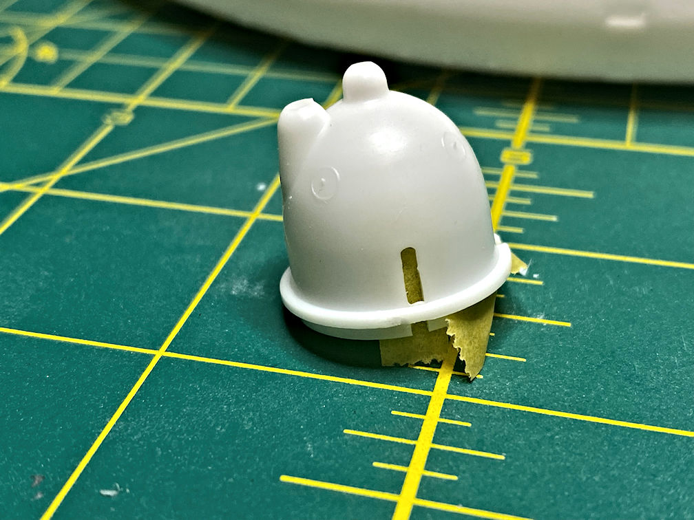
I have placed tape behind the cutout so it will be a bit easier to fill the gap.
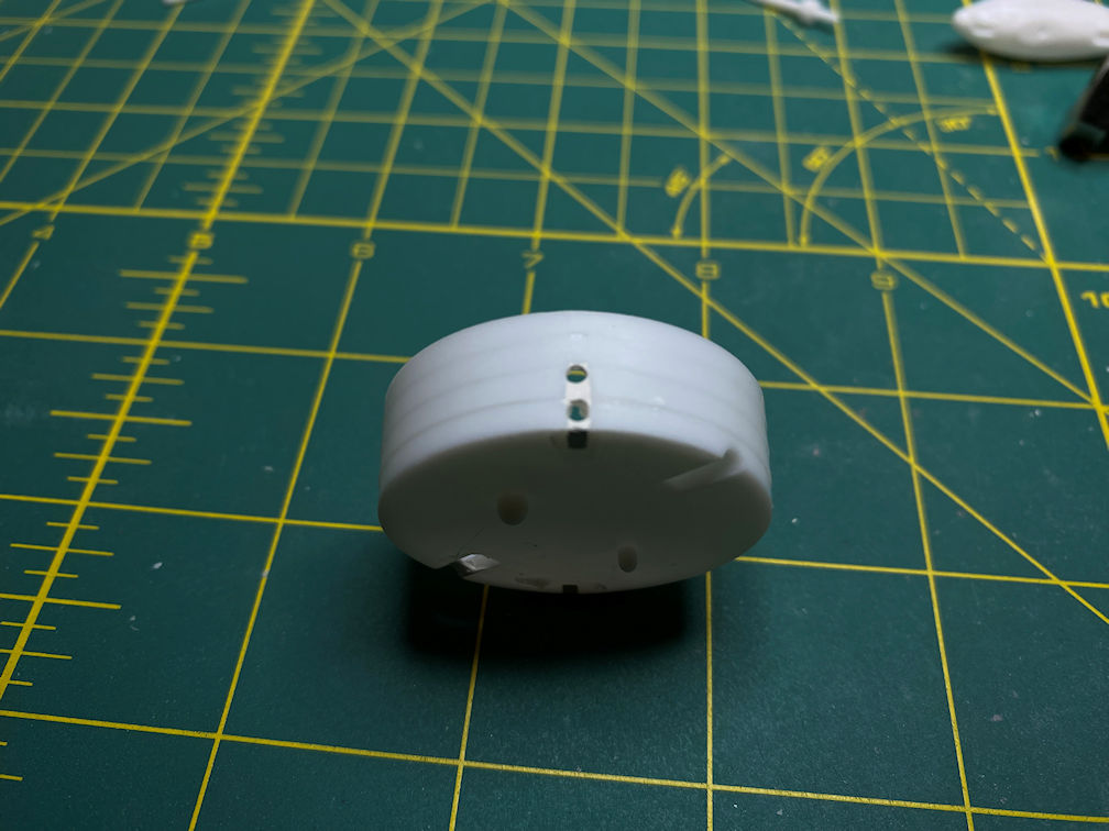
The opposite side was supposed to have the same rectangular cut out but instead it was filled in and has a slightly raised area where the rectangle would have been.
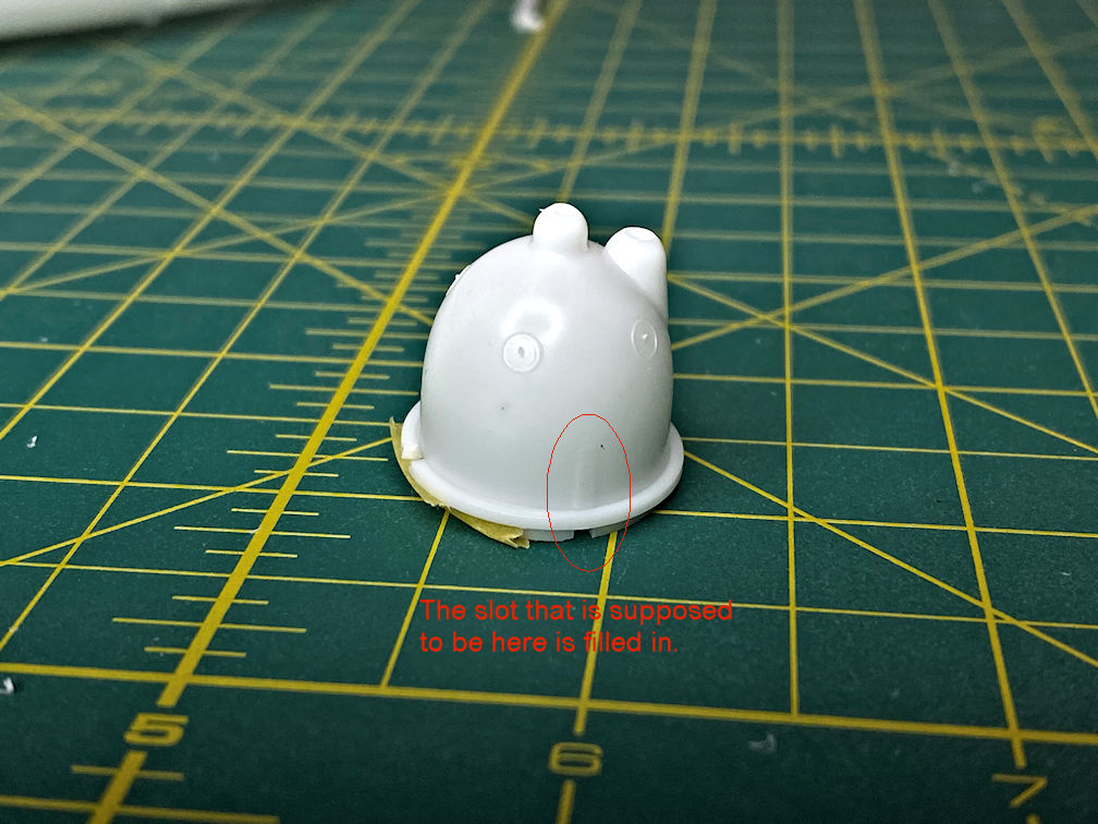
I’ll smooth out the raised area so it wont be visible.
There is also a strange square cutout on one side that does not correspond to any part. I’ll fill that in as well.
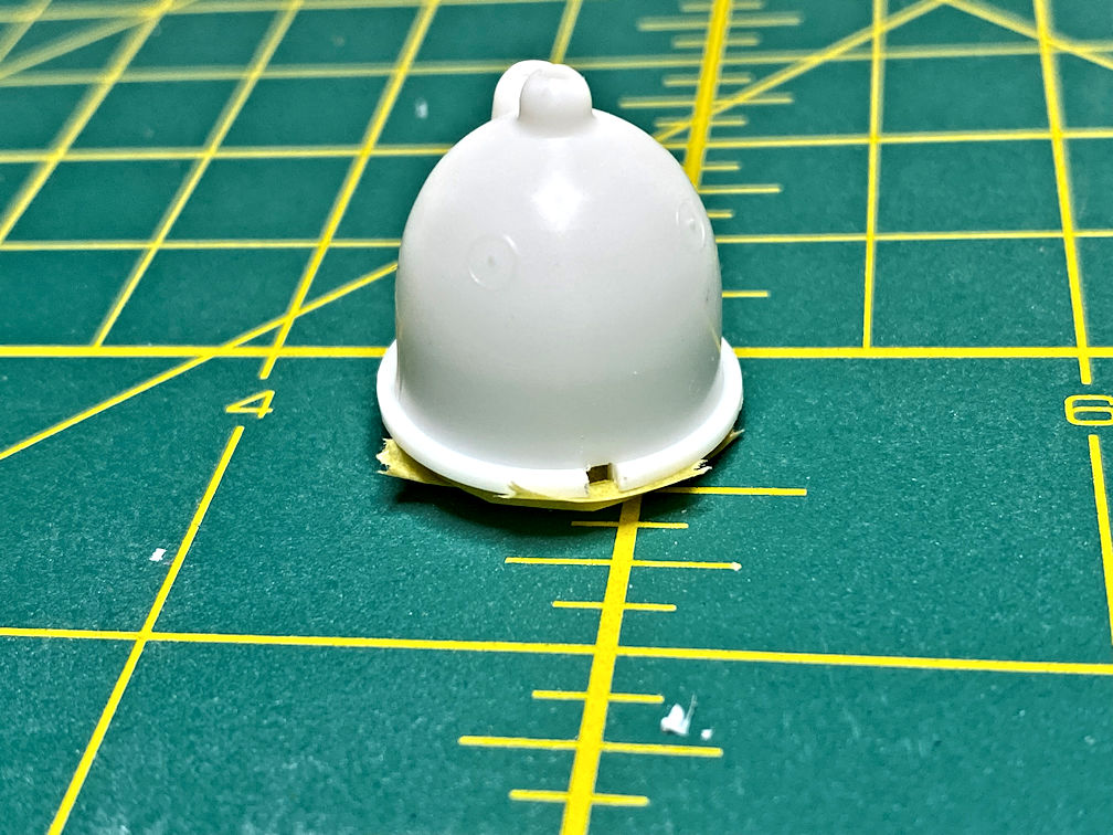
I then needed to drill holes for the conduits that will be added later. I drilled two 1/16 in. holes in the side I had filled first. I test fitted the conduit and it looks like it will work.
I then drilled the same 1/16 in. holes in the opposite side where the slot was already filled in with plastic. A test fit showed the conduits needed a bit of trimming to fit.
I also filled in the slots in the air lock that fits on the upper side of the hub of the station. There will be conduits that fit in here as well.
I then drilled 1/16 in. holes in the air lock part as well.
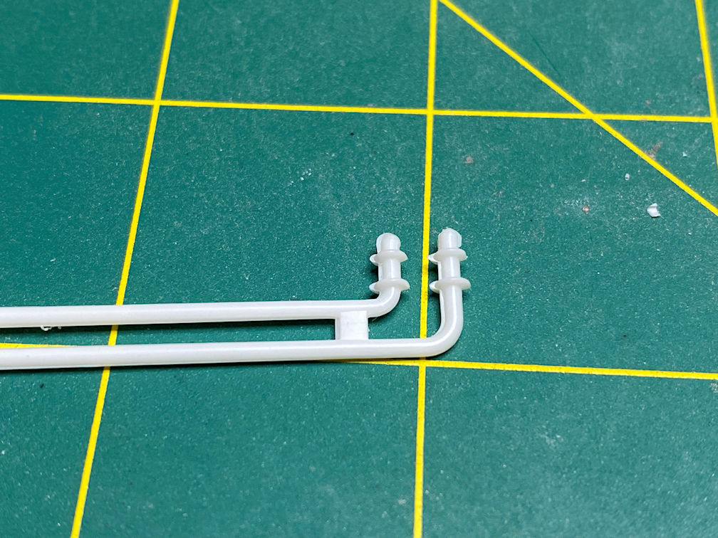
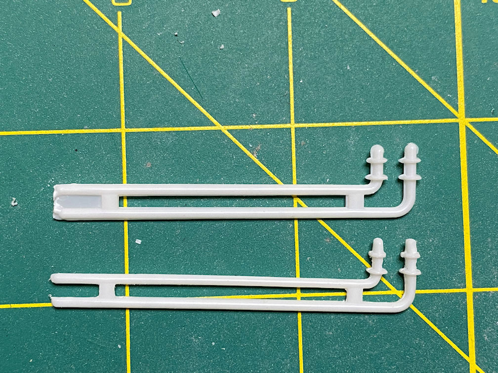
I cleaned up the two storage tanks, the conduit and supports that connect them to the station. Here is a photo of them after cleaning.
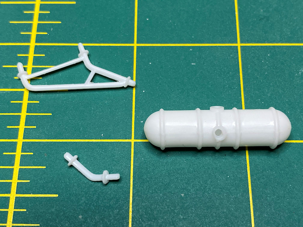
I did a test fit with the station. The conduit is on the left and the braces are on the right.
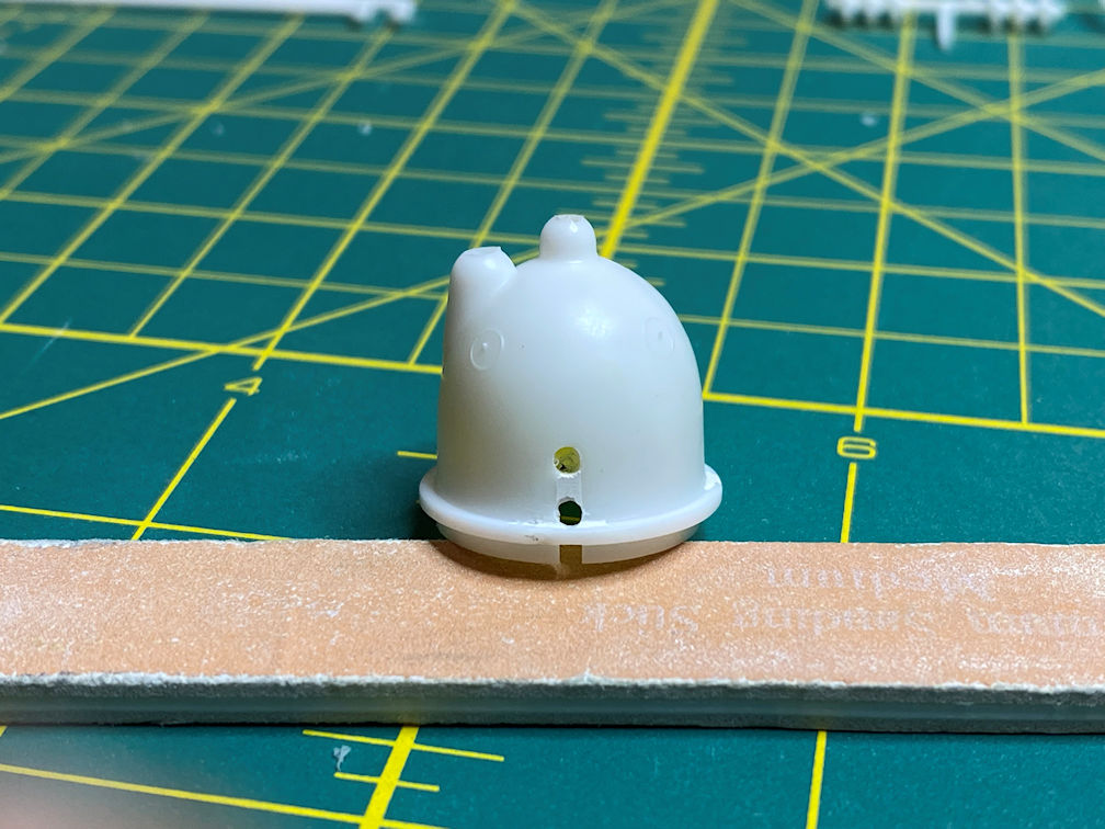
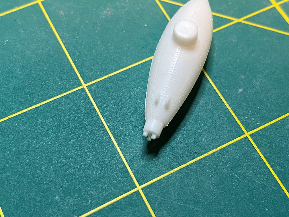
Next I put together the two space cars. I didn’t pay attention to the part numbers and cut off a top and a bottom and started to test fit them. I couldn’t get the parts to fit together. It turned out the the locator pins and holes did not line up. The aft hole was on the opposite side of the part from the pin. I then realized that the parts were keyed differently. I cut off the other top part and sure enough the pins and holes lined up. It seems funny that the parts were keyed as if there was a left and right one but the part numbers are the same.
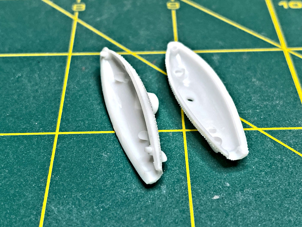
I glued the two halves together and then noticed that at the aft end there was a slight mismatch.
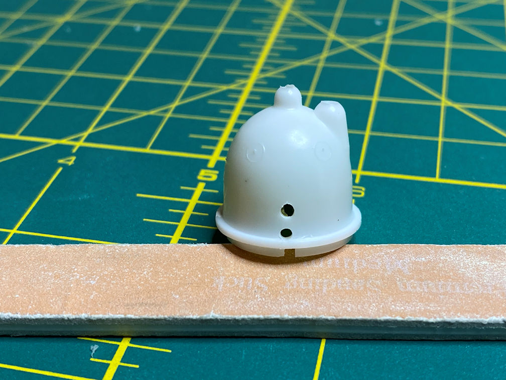
I trimmed that up and then checked out the hole in the aft end. The hole wasn’t centered on the aft end it was off to one side.

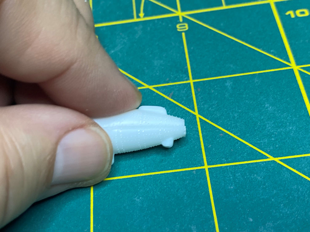
That got me to wondering about the space car exhaust part. I cut one off the tree and looked at the side with the pin. Sure enough the large pin is not centered the part either.
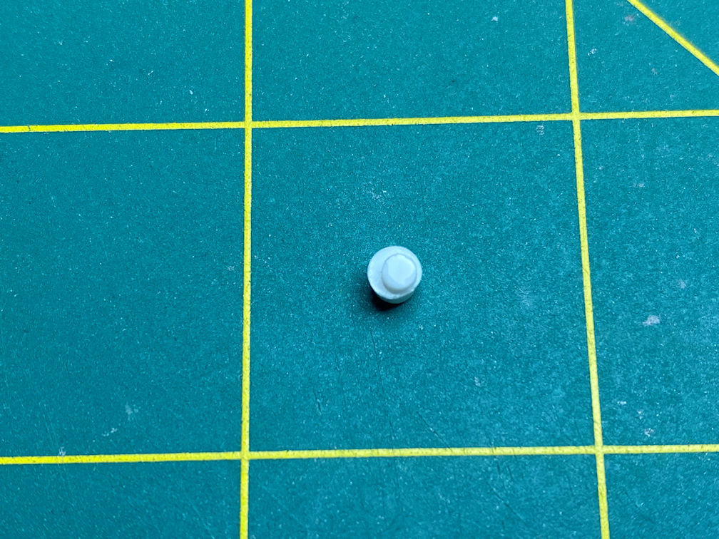
I dry fitted the part and saw that the off center pin was keeping it from centering with the space car. I rotated the space car exhaust until it was centered. It fit nicely and I glued it into place. When I was done with both space cars I found that the exhausts on each space car were in an opposite orientation from the other. Oh well, now they will have a distinguishing feature.
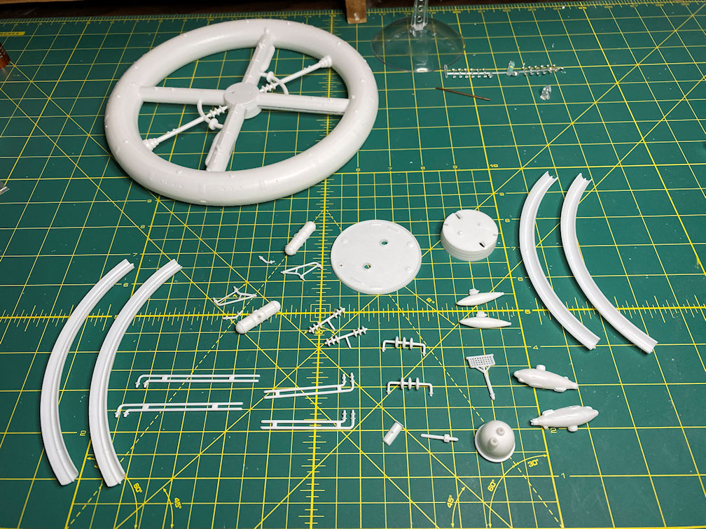
Here is a photo of all the cleaned up parts.
Next up will be starting the painting process with primer.
Thanks for looking.

One thought on “Lindberg Space Base Build”