

While I was working on the Soyuz build I had been thinking about my next build. I finally came to the decision to do a 1/72 scale US spacecraft set. When it is done it will consist of a Mercury, Gemini and Apollo spacecraft. I’ve already built the Mercury part of the build back in November of 2021. Now I’ll start on the Gemini part. The only injection molded kit in 1/72 scale is the now discontinued Dragon kit. Realspace Models has a very nice resin kit in 1/72 scale as well, but I don’t have that one in my stash. The Dragon kit has options to build it with a space walker or with both hatches closed. I’ll be modeling it with hatches closed. Many flights of the Gemini program had the spacecraft with some visible differences. I haven’t yet decided on exactly which flight I’ll be modeling.
Here is a photo of the kit parts.

The parts are well molded. The astronaut figures are made from a soft bendable plastic that I’ve heard can be glued with typical model cements and can be painted like normal plastic. When I first saw them I was afraid that they were vinyl which is not easy to work with, but this is apparently not the case.
The hatch windows are molded solid so you cannot see through them. I decided to start there. Here is a photo showing an original and one where I’ve cut out the window.

I next tackled the engraved lines on the adapter sections. For some reason, Dragon opted to model the black stripes seen on early spacecraft as engraved lines. In reality they were hand applied tape strips for thermal control. The engraved lines are fairly deep. I first tried using Mr. Surfacer 500. It is easy to apply but it shrinks a lot. I also tried using Tamiya white putty. It shrinks less that the Mr. Surfacer, but it’s harder to apply. Here is a photo of my testing of the two filler methods. The Mr. Surfacer is nearly the same color as the plastic.

Both methods work pretty well but take several passes to get them completely filled. Then a light bulb went off. What if I put some styrene strip stock in the grooves and then trim off any excess and sand down any raised areas. That worked great and was much faster to do. Here is a photo of the strip stock filler.
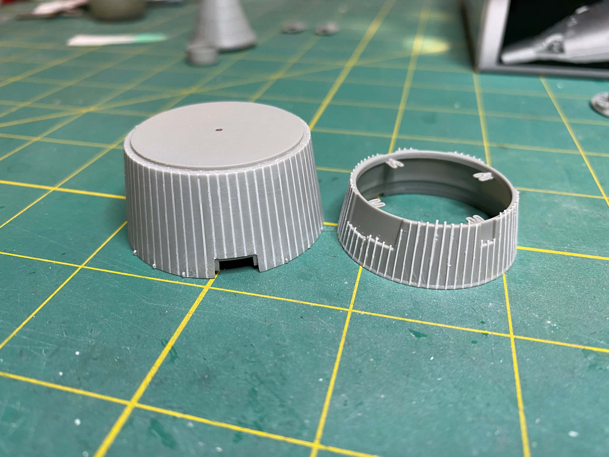
On the right is the retro adapter section. It has the strips applied but not yet trimmed or sanded. The one on the left is the equipment section and it has been trimmed and sanded.
Having finished that tedious task, I started on the astronaut modifications. The kit gives you two figures. One in a seated position and the other in a spacewalk pose. Since I’ve decided that this model will be with doors closed, I need to re-pose the figure. This requires quite a bit of surgery. The spacewalking figure is also a bit larger in body build to the seated figure. I shaved a good deal off the hips and thighs. I also removed a bit of crotch area in order to glue the legs together so he would fit the seat. It seems that it is true, the soft plastic reacts with the liquid cement that I’m using just like hard plastic. Next, I cut a bit from the top of the thighs near the hip to get them into a more 90 degree angle. Finally, I cut some out of the back of the knees to get a good bend that would fit the seat. Here are a couple of photos to show the finished product.

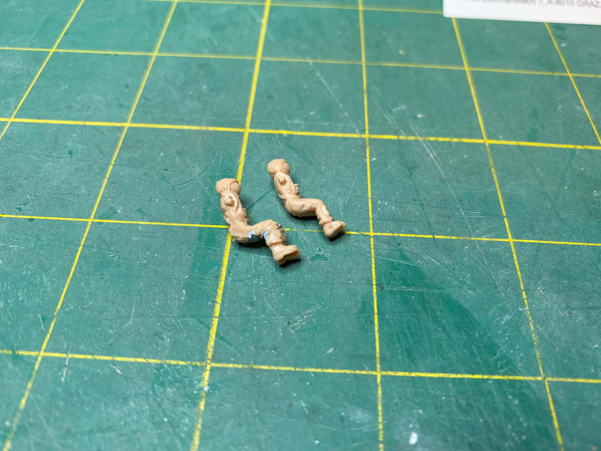
I used some Mr. Surfacer to fill some of the sliced areas. I also used some on both astronauts where they had a molded depression in their chests. Their arms will be added later after I get the cockpit built so I can be sure their arms do not interfere with anything. The spacewalker’s right arm will also get the maneuvering gun removed.
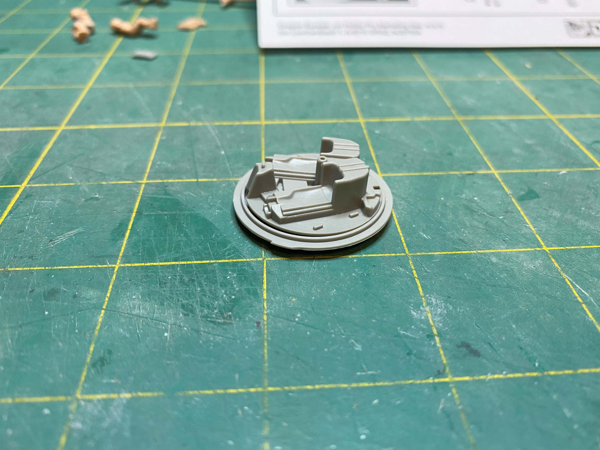
I moved back to the retro adapter section to add the thruster packs and cable cutting assemblies. The two thruster/cutter packs had some strange pegs on their backs which had to be removed before assembly.
The rest of the bits fit well and will not need much filling. Here is a photo.

I decided that rather than use the included stand I’ll drill a hole through the lower single thruster and use that with a metal rod to attach the model to the base. I’ll do that a bit later since I need to get some 1/16 inch steel rod first.
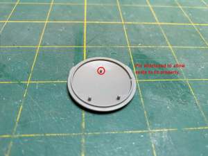
I continued the build with the heat shield and back cockpit wall. The heat shield has three pins to properly position the cockpit wall. Unfortunately, the top pin is too tall. It keeps the cockpit wall from going all the way into the heat shield. Here is a photo that shows the problem.
I trimmed off the pin a bit until the cockpit wall fit properly.

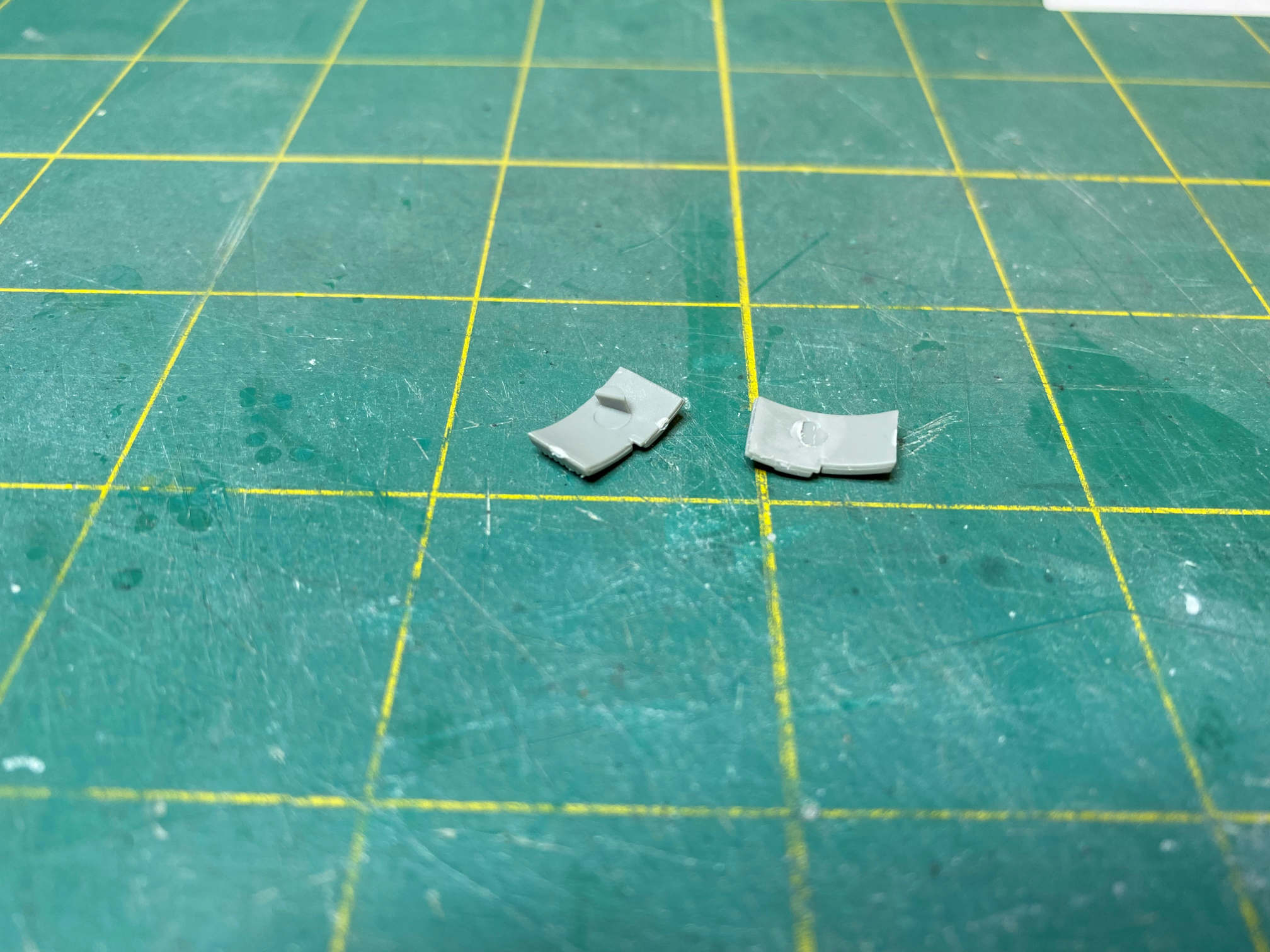
Since I’m building an in-flight version, I need to fill the hole in the side of the re-entry section that would otherwise have the horizon sensor cover attached to it. I’ll try to fix the shingles in that area with some 0.005 in. sheet stock. Also notice the tiny indentations that represent the re-entry thrusters.

I used a pin vice to enlarge the holes to a more scale size. The indentations did help to make sure the holes I drilled were in the proper place.

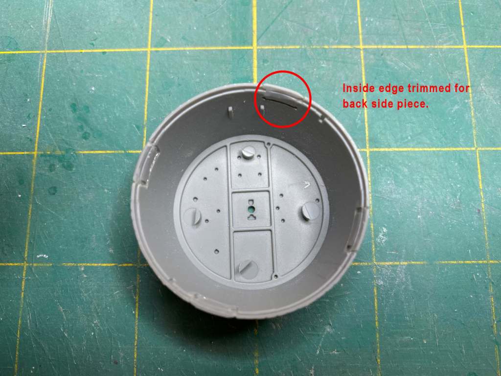
Moving over to the equipment adapter section, I test fitted the roll thrusters to their holes and found that they sat raised quite a bit above the rest of the adapter section. They should be flush, other than the actual thruster housing itself. The problem is that the mounting tabs are too thick for the part provided. I chose to remove the tabs. Here is a look at the problem and the fix.
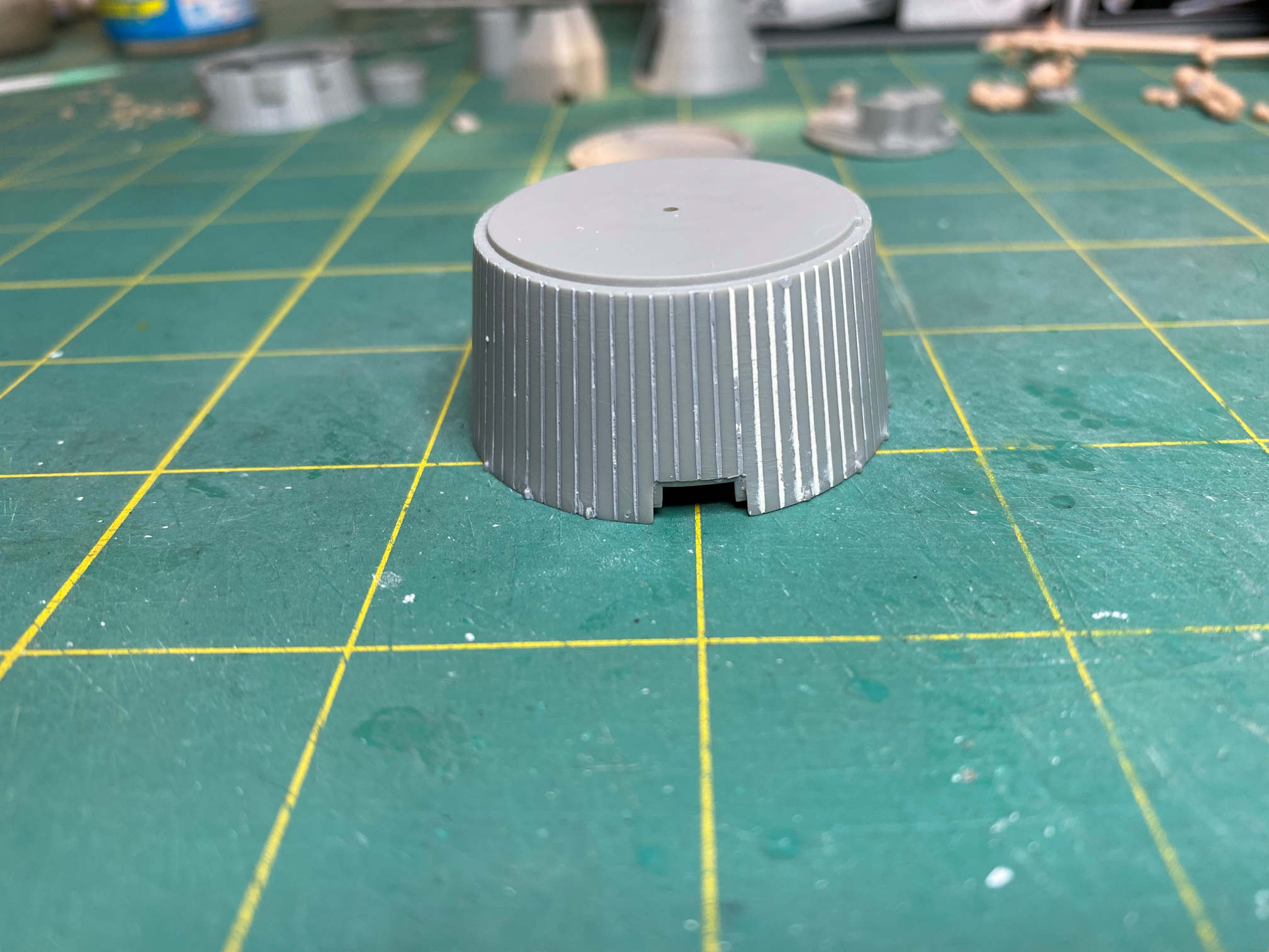


They fit pretty well now. It will take a bit of sanding and some filler to finish them off. I test fitted the adapter section cover to see how well it fit. It seemed pretty close, but I couldn’t get it to seat properly. I looked closely and found that, as a result of removing the mounting tabs, the thruster packages that I installed sat a bit deeper than designed. This required shaving a bit off the back of each thruster pack piece. Another test fit showed that it fit better but something was still getting in the way. This time I shaved a bit off the inside edge of the cover where it met the thruster housings. That did the trick. Here is a look at the solution.

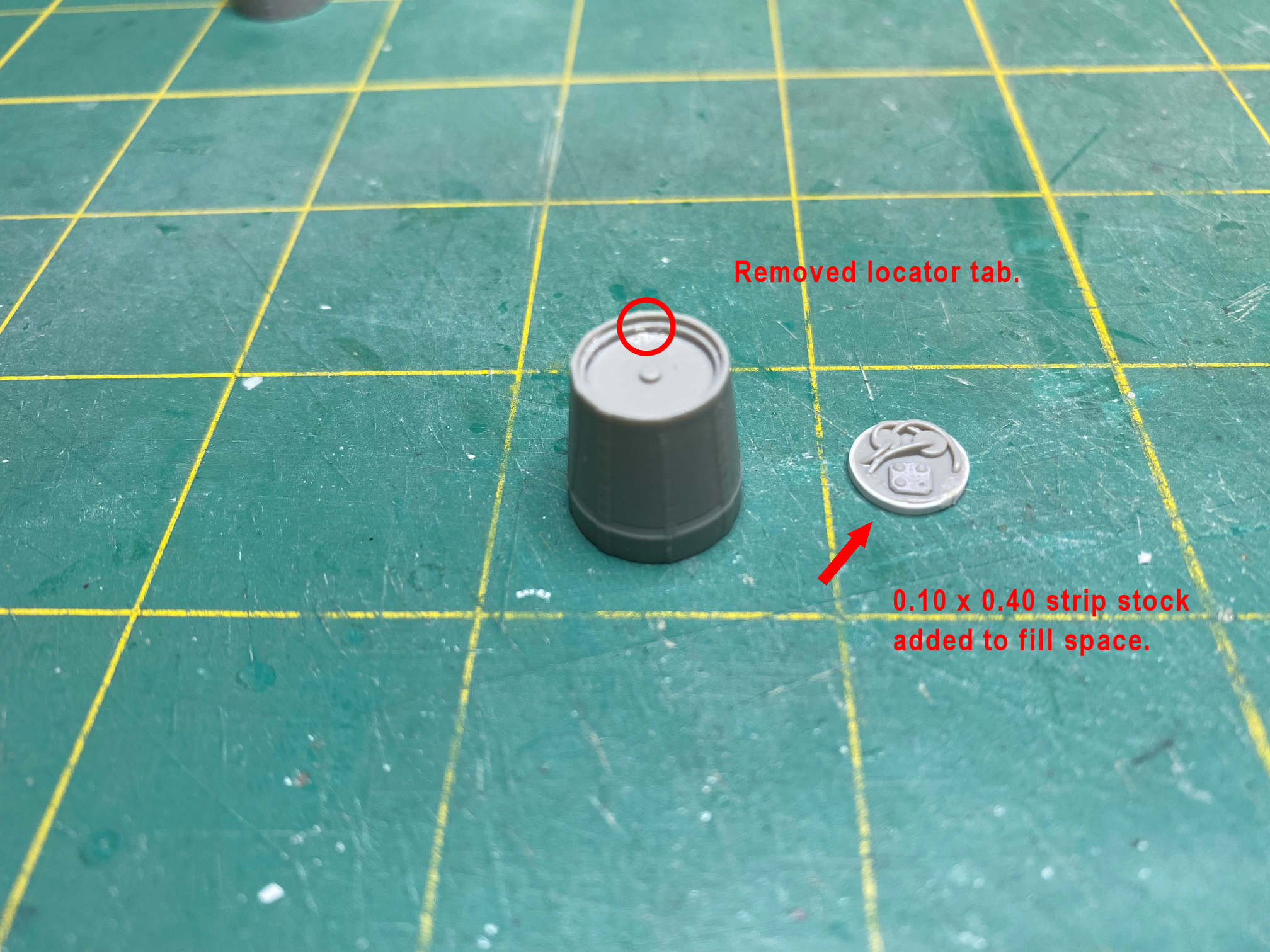
The recovery section needed a bit of attention as well. The part that represents the tip of the recovery section has a locating notch for the insert. But the notch is about 90 degrees in the wrong direction. I removed the locating notch so I could orient the insert as needed. The insert also needed attention. Its diameter is too small for the hole it is put in. I glued a strip of 0.010 x 0.040 inch styrene to fill the gap. It fits nicely, but I won’t install it just yet. It fits so well that I might not get it back out, so I’ll wait until the nose gets glued on first.
That does it for now. More to come. Thanks for looking.
