
I glued the rear bulkhead to the Service Module. The rear bulkhead does not cover the full circle of the cylindrical SM. To fix that I glued on a strip of 0.040 x 0.010 strip stock to fill the gap and then sanded off any extra.

Next I folded the SM/SLA Electrical Umbilical Disconnect PE part and glued it to the rear bulkhead.
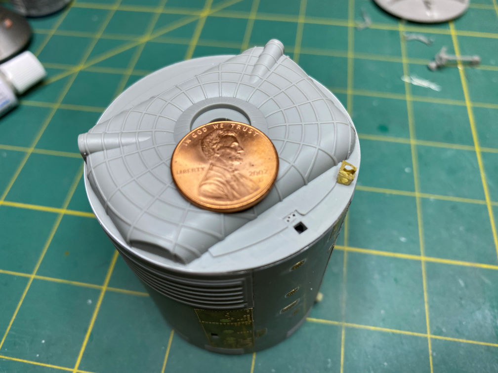
I also drilled three small holes into the rear bulkhead for some wires that will run from the Umbilical Disconnect to the base of the high gain antenna array. I also drilled a small hole into the base of the of the high gain antenna array mast for an additional wire. The wires will be painted white and added after the antenna array is glued in.
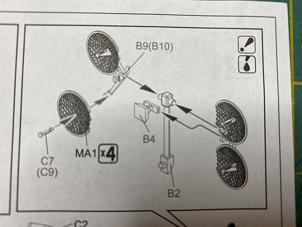
I then moved to the High Gain Antenna Array. If you look at the instructions, they call out parts that don’t match the illustration anymore. Parts B4 and B9/B10 are radically different from what the illustration shows. Even part B2 is different. Part B2 has holes instead of pegs on the antenna end. Those new holes are for the pins that are now part of the new B9/B10 parts. The parts C7/C9 are on the tree but they are redundant now. The new parts B9/B10 have the C7/C9 parts already molded together as one piece.
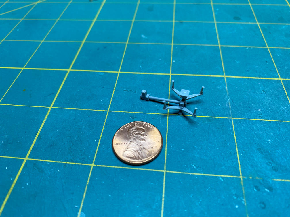
Here is a picture of the actual parts. I’ve already attached the horn (B4) to the mast (B2). It is a snap fit to allow positioning of the antenna array after assembly. I guess it’s another sign that this kit was rushed through to production or just crappy QC.

It was about at this point that I realized that I had assembled the New-Ware EVA light incorrectly. I assembled it in a folded position. That would be correct if I was building it in launch configuration. Since this is being modeled in an in-flight mode, the EVA light should be extended. I didn’t realize that the EVA light extended as soon as the BPC was jettisoned during launch. Yet another interesting fact found out while researching a model. Anyway, this is how it should look. I’ll attach it after most of the assembly is done, otherwise I’m sure I’ll just knock it off.

Then back to the high gain antenna. Here you can see the finished antenna framework.
Next was to put a curve into the flat PE antenna dishes. New-Ware does not provide anything to help make the flat PE antenna curve to the proper shape. I scrounged all over the house trying to find something with a decent curve that I could use to press the PE into the right shape. I found an old mouse ball that looked good but then I needed a concave object with an equally good curve that I could press the flat part into with the mouse ball. I finally found a measuring spoon in a box of junk that our son brought back from college years ago. I found a mallet that I could use to tap on the mouse ball in a box of old leather working tools.

So here is a close up of the finished product. I think it will work.

That’s it for now. Thanks for looking.
