
Well construction is done on the Discovery XD-1. I made my goal of finishing it before Christmas (if you don’t count the stand). I’m still working on how I want to display it. I don’t know if I’ll use the stands that are included in the in kit or if I’ll try to find something else. It is quite a long model and takes up a fair amount of space. I may try to find a solution that allows me to hang it from the wall. Anyway, when I come up with something I’ll probably post an epilogue on it.
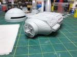
I glued the forward neck sections together and added the spine connecting piece to the reactor section.

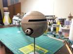
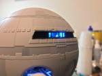
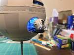
With painting complete I removed the remaining masking and started installing the interior of the command sphere. I first installed the window shelf before using CA glue to place the cockpit in the upper half of the sphere. I then applied some JB Weld epoxy around the edges as an additional light blocking and to permanently attach the cockpit.

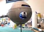
Next came the pod bay installation into the lower sphere half. Here I needed to make an adjustment. If i tried to place the pod bay in where it fit then the extended pod platform wouldn’t fit since I had included the door frame. If I had left off the door frame then it would have been fine. To fix it. I installed the pod bay just a bit higher in the sphere half. This meant that the bottom of the interior would not rest in the bottom of the sphere. This would lead to a very weak attachment at just a couple of points at the top of the pod bay. To sturdy it up, I added some styrene extensions to the bottom of the pod bay. They were at first attached with CA then after the pod bay was properly glued in, I used some JB Weld to more permanently attach them. It is now installed very firmly to the sphere.

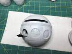
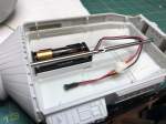
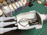
Next I glued the two sphere halves together with some Tenax. With the sphere together I, soldered the cockpit and pod bay wires together and then added the long wires that will travel the length of the spine back to the batteries in the reactor section. I then threaded that wire through the command sphere back plate and glued it to the command sphere.


I then turned my attention to the steel rod that went into the reactor section. I needed to create an opening in it to allow the wires to exit the spine and get attached to the battery switch. I used my Dremel tool to grind of a section and then used a file to remove the sharp bits.
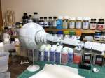
Now I could start building the spine to put the rest of the model together. I used a bit of JB Weld epoxy in the back of the command sphere where the forward rod was to go. Then I threaded the wire through the rod and put the rod in the command sphere back. Next I glued the neck section to the command sphere back. This would also help center the rod in the command sphere back since there was a bit of play at that joint.

I was then able to start adding the spine sections with CA. The forward section was finished with the addition of the antenna complex. The antenna complex also contains the rod connecting sleeve. I glued the sleeve to the forward rod with a bit of CA trying my best to get the antenna section lined up properly with the command sphere.

Then I moved on to the the rear section of the spine. First was to thread the wire through the rear rod. I had to slide on the spine sections and reactor section even though I would not be gluing them at this time. This was necessary to make it easier to get the wire through the small hole in the rod. I then applied CA to the rod and sleeve in the antenna array. Now I could start gluing the spine sections as earlier for the forward section. Finally the reactor section was glued in place.
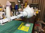
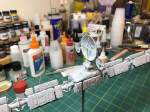
Next came adding the containers. This required special attention to the instructions to be sure that they were glued on in the proper order Some of the sections were a bit trickier that others since they had only one attachment point and a large over hang on one side. But it all went well and surprisingly enough I didn’t have to redo any containers.


Once the containers were on I used some black wash on the engine exhausts, glued then in place in the engine stalks and then glued the completed engines to the reactor section. Unfortunately the engines do not touch each other as they do in the film. I couldn’t come up with a satisfactory fix so I just left them with a small gap between each other. I also soldered the wires together in the reactor section which completed the wiring process. The pictures show the lighting bluer than it actually looks.

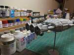


I epoxied the stand sections to their steel rods and sprayed them with primer. I believe I will paint base and rod matte black and the top piece I’ll paint with the base color of the model. Like I said at the beginning I’m still not sure exactly how I will finally mount it.
That was a fun build and I really like the final product. Thanks for following along.
